
Trochograph
structprints

AI找相似


打印配置(0)
模型文件(0)
 0
0 0
0 0
0
发布时间:2026-01-30 16:42:17
0
0
 000
000Something always worries me when looking at electronic circuits. Of the three kinds of passive components: resistor, capacitor, and inductor, the last one is always far less represented than the first two. Why ?
After some thinking, I have starting to speculate that maybe the difficulty of plotting a nice inductor symbol by hand (compared to other components for which drawing templates are easily found) makes electronic engineers reluctant to integrate them in their designs. A few of them cheat by using a poor cycloid looking representation for inductors, which can be achieved with a template but somewhat ruin the beauty of electronic schemes.
This should change with the invention of the trochograph, making trochoid drawing an incredibly easy task for anyone. Time has come for a new electronic revolution that will bring harmony to all PCBs in the world !
https://vimeo.com/951996632?share=copy
A trochoid is a curve corresponding to the trajectory of a point of a rolling disk. More precisely, for prolate (or extended) trochoids (the ones with loops), this point is outside the disk, farther from the center than the circumference of the disk (the pitch circle).
Curves with loops cannot be easily drawn with templates, because we would need an unconnected template.
The intuition behind the trochograph is to use a gear rolling on a rack, similarly to how a classical spirograph uses a gear rolling on an internal gear. This would work for curtate (contracted) trochoids, and racks are actually included in the “super spirograph” set. For a prolate trochoid however, the pen tip would need to be outside the pitch circle, which can't be done with a simple gear.
So instead of having the drawing gear directly rolling on the rack, we engage the drawing gear with a second gear, itself joined with a smaller pinion rolling on the rack, thus providing a reduction factor. The relative positions of the two gears is maintained by a slider part.
The default parameters (used in the provided STL) will give you a credit card sized tool, which makes trochoids with 3 loops, about 20mm long (including the ends) and 5mm wide, suitable for drawing inductors in electronic schemes.
This model is not extremely hard to print, but requires a good printing accuracy. I had good results with PETG, but PLA works too.
All parts can be printed with a 0.2mm layer height (parts thickness are multiples of 0.2mm by default). A smaller layer height will also work. I used 2 perimeters, 0.6mm bottom/top, and 20% infill.
A low speed and efficient cooling are required for printing the gears accurately: I used 10mm/s for wall speed.
The top surface need to be as smooth as possible, so you should avoid over-extrusion, and the bed must not be too high (maybe slightly increase the Z offset). I didn't try ironing. I also disabled “Fill Gaps Between Walls” in Cura, which only pollutes the print with useless travel moves for such parts.
Horizontal play varies a lot between printers, print settings, and filaments, so you may need some adjustment to ensure smooth operation without excessive play.
One way to adjust tolerances is by customizing the play parameters in OpenSCAD, specifically the shaft_play, teeth_play, and rail_play values. Gears must move freely in the corresponding holes in the slider (shaft_play), and not be pressed too much against one another (teeth_play). The downside of this approach is that the play parameters affect the slider, top, and bottom parts dimensions.
Another option is to tune horizontal expansion when slicing. While less flexible, this can allow you to re-print only the gears (except if the rail's fit is too tight).
First place the gears in the bottom part as in the following picture:
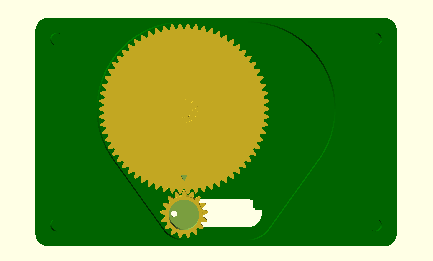
The hole in the trochoid gear must be oriented left, and the triangle on the large gear must point to the bottom. Both gears must be flushed to the left. Add the slider without moving the gears.
Then put the top part. The pinion's two bottom teeth should mesh with the rack's second tooth (the first “full” tooth):
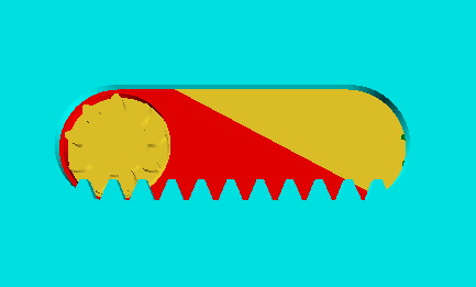
The trochoid radius and ratio can be customized (indirectly for the latter), as well as many other things. Only prolate trochoids can be drawn, with sufficient self intersection, due to friction considerations.
To minimize friction, the radius of the shafts, small gear, and pinion, should be minimal. So, the pinions number of teeth is 9 by default, which is about the minimum possible number (with a 25° pressure angle). The tooth size should also be as small as possible without causing meshing issues due to the play between parts. I found that 1.5mm was barely sufficient. A tooth size around 2mm is OK. Finally, the trochoid gear's outer radius should also be as small as possible to minimize overall size and friction, so its number of teeth is computed as the minimum value for the specified trochoid's radius (plus pen tip radius and clearance).
The trochoid radius (which corresponds to half the "width" of the plot) can be set directly. The number of loops is an input parameter too.
Then, you should change the top gear's number of teeth to obtain the desired “pitch” between loops (computed pitch value is displayed by the OpenSCAD script). The trochoid's total length is equal to the product of the pitch and number of turns and a half, plus twice the radius. It is also displayed.
Another useful parameter is the slider length, which should be long enough to avoid excessive play and friction. The case dimensions are computed from other values by taking the bounding box.
The spirograph drawing tool has been known for decades, and I when looking for similar things I discovered the super spirograph which has racks (among other things) and is therefore able to draw contracted trochoids. However, I'm not aware of any existing description of the design presented here, or any similar way to plot extended trochoids, so I consider it as new until someone points me to a prior construction !
