
Neptune 4 PC4-M10 Fitting Attachments
SleekTower

AI ile Benzer Model Bul


Baskı Profili(0)
Model Dosyası(0)
 0
0 0
0 0
0
Yayınlandı:2026-01-09 22:20:59
0
0



 000
000I designed these models for a project with my Neptune 4. I have moved my spool from the original spool holder that hangs on top of the printer to a spool roller inside of a filament dryer that sits on top of the enclosure of the printer. I used to just have a hole with a filament guide to feed filament into the enclosure and to the printer.
The aim of this project was therefore to create a fully enclosed, well-defined, smooth filament path from the dryer to the extruder. Of course, it is possible to simply use a long piece of Bowden tube between the dryer and the extruder. But, the Neptune 4 came with a Filament runout sensor that sits between the spool and the extruder. I would like to still be able to use this sensor. As such, I designed a few small attachments to mount PC4-M10 pneumatic fittings on top of my enclosure, on the filament sensor, and on the extruder feed itself.
I printed everything in PLA, but perhaps PETG would be better, especially for the piece sitting on the extruder.
5x PC4-M10 pneumatic fittings
2x M3 nuts
2x M3 screws (length is your choice)
2x 2.8mm wood/plastic screws (self-threading screw) 12mm length
1m of 4mm OD Bowden tube
Some sandpaper, low grit is fine
Some lubricating grease
Some VHB temperature resistant double sided tape
Tubing cutter
Wrench
Hammer
Screwdrivers
A simple cylinder model intended as a filament guide tube at the bottom of the pneumatic fitting. The Bowden tube doesn't go through the whole length of the pneumatic fitting, so, there are several millimeters after the Bowden tube ends, where the filament has a lot of freedom to move laterally due to its inherent curvature. This is a problem when the filament has to enter another well-defined hole after exiting the Bowden tube. So, this cylinder is there to bridge the Bowden tube and the hole after, creating a straight and constrained filament path.
0.1mm layer height and first layer, aligned seam, brim enabled, spiral vase, 1 perimeter, no top, and bottom layer, 0.4mm extrusion width.
The height of the tube given in the STL file is arbitrary. You can scale the Z-dimension to suit your needs. For the filament sensor, a tube length of 11.25mm works for me, and for the extruder, a tube length of 12.5mm. I would suggest printing longer tubes than you need, measuring the length you need, cutting, and then sanding. In my experience, any slight elephant foot would result in the tube not fitting, so, I would recommend also sanding these away.
Cut a small piece of Bowden tubing and insert it into your pneumatic fitting. Then, insert the guide tube from below the pneumatic fitting until it hits the end of the Bowden tube and can go no further. Some of the guide tube should stick out so it can go in a bit into the next hole, be it another pneumatic fitting or a hole in a brass fitting.
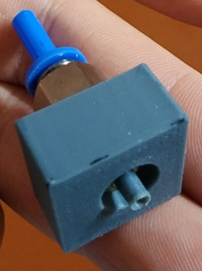
This is a pair of attachments that in principle can be used to create a filament passthrough across any flat thing of any thickness using a couple of PC4-M10 pneumatic fittings and some Bowden tubing, as long as you can find the appropriate length M3 screw. The holes for the pneumatic fitting is unthreaded. I have tried experimenting with designing and printing threaded holes, but I have not managed to get it working well. Feel free if you want to suggest something or try and make a threaded print for this. One of the attachments has hexagonal holes where the M3 nuts would sit. If you have 2.3mm thick M3 nut, it would sit flush. The other attachment with the circular holes are designed for M3 screw with 5.4mm head diameter and 3.1mm head thickness to sit flush. You need this print and one piece of the “PC4-M10 Filament Guide Tube” adjusted in Z-dimension to whatever length you need to bridge for your passthrough.
Use a wrench to screw in the fitting. Only screw in until the bottom of the fitting sits flush with the print. Do not overtighten as it will crack the print. Repeat this multiple times until you can screw the fitting in and out relatively easily. I would recommend lubricating the hole after with a tiny bit of grease so it is easier to screw in and out. You will also need to use the hammer to get the M3 nuts into the hexagonal hole as it may be a bit tight. Install the guide tube using the method described above. Drill a hole big enough for the guide tube to go through whatever you are passing through. Align the two pieces by making sure the guide tube is bridging both pneumatic fittings. Finally, screw them together.


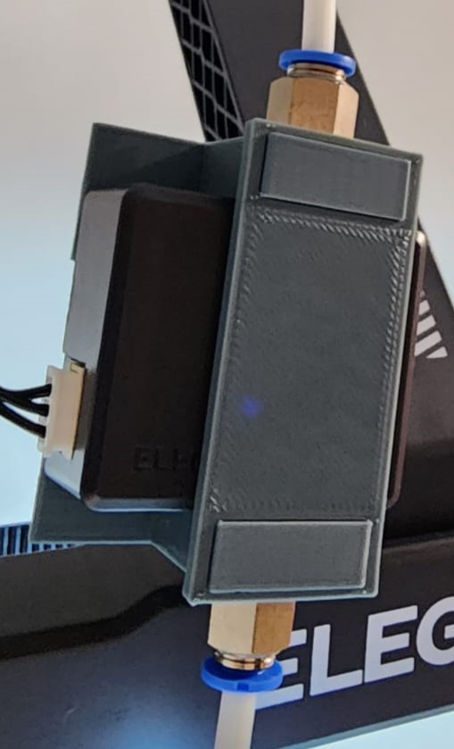
This is a set of attachments for mounting PC4-M10 pneumatic fittings onto the inlet and outlet of the filament sensor of Elegoo Neptune 4. The design is specific to the Neptune 4, and I don't think it will work for anything else. The hole for the pneumatic fitting is identical to the other attachments. The two attachments with the hole for the pneumatic fitting are orientational, one will only work for the inlet and one will only work for the outlet. this mount using an existing screw hole of the filament sensor. On the back of the sensor, you will see two self-threading screws. You are going to remove these and replace them with 2.8mm self-threading screw of 12mm length. The third piece is a front plate to link the two attachments and secure them better since they are only fastened with a couple of screws at the back and tend to lift up a bit. You need this print and two pieces of the “PC4-M10 Filament Guide Tube”, each 11.25mm long, in my experience.
Use a wrench to screw in the fitting. Only screw in until the bottom of the fitting sits flush with the print. Do not overtighten as it will crack the print. Repeat this multiple times until you can screw the fitting in and out relatively easily. I would recommend lubricating the hole after with a tiny bit of grease so it is easier to screw in and out. Install the guide tube using the method described above. Use the guide tube to align the attachment with the brass hole on the inlet and outlet of the filament sensor. When you do it properly, the screw hole of the filament sensor should line up with the screw hole on the attachments and you can screw them together with the longer self-threading 2.8mm screws. Lastly, slide the front plate to join the inlet and outlet attachments.
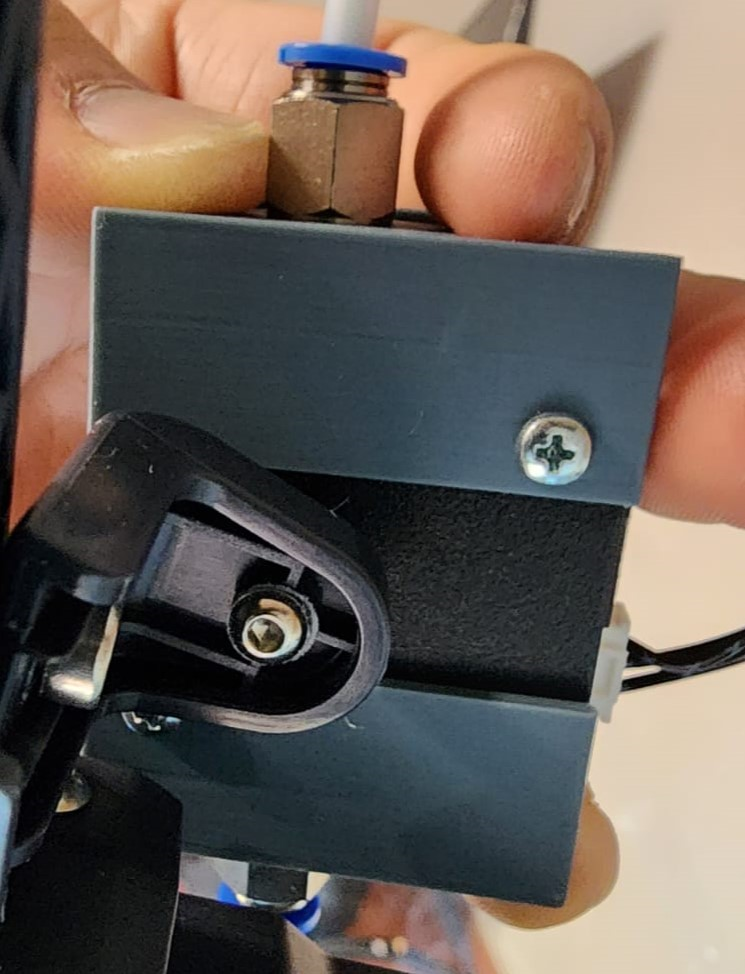
This is a simple slab model with a hole for mounting PC4-M10 pneumatic fittings onto the feed of the Elegoo Neptune 4 extruder. There is no mounting mechanism of this attachment to the extruder as I could not figure out a simple way to do so. Feel free if you want to suggest something for this. The design is specific to the Neptune 4, and I don't think it will work for anything else. The hole for the pneumatic fitting is identical to the other attachments. You need this print and one piece of the “PC4-M10 Filament Guide Tube”, 12.5mm long, in my experience, but this may depend on how thick your double-sided tape is.
Use a wrench to screw in the fitting, and do it all the way until the fitting bottomed out. Do not overtighten as it will crack the print. Repeat this multiple times until you can screw the fitting in and out relatively easily. I would recommend lubricating the hole after with a tiny bit of grease so it is easier to screw in and out. Cut and stick your double-sided tape. Install the guide tube using the method described above. Use the guide tube to align the attachment with the brass feed hole of the extruder and then stick them together. The hole for the fitting is intentionally off-center. You will see that one side between the hole and the side of the slab is the thickest and this side should be towards the front.
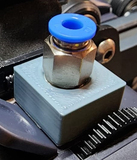
Please note that I made this based on my screws, nuts, pneumatic fittings, etc, so, there is a chance that it may not be fitting perfectly for you. Let me know if this is the case!
Happy printing!
