Этот контент был автоматически переведен. Показать оригинал
Abstract
CircuitMate is a multifunctional electronic calculator designed to assist with various electronic calculations, such as resistance and capacitance values.
CircuitMate: an electronic calculator
Function
You can find the source code and firmware of CircuitMate in this GitHub repository:CircuitMate GitHub repository。
The current firmware includes the following features:
- Resistance Calculator:
- DIP resistor calculator
- SMD Resistance Calculator
- Capacitance Calculator:
- Supports 3 ceramic and SMD capacitors
- Games:
This firmware is designed to be scalable, allowing users to easily add new applications
Design objectives
When designing CircuitMate, there were several key objectives that guided the development process:
- Practical and useful:A simple interface that enables quick and efficient use.
- Intuitive:User-friendly layout and controls.
- Bill of Materials (BOM):Design with the fewest and easiest-to-procure components.
- Easy to build:The assembly process is minimized.
- ScalableIt can be easily modified or expanded to add more functionality.
Overview of documents and parts
- Base.stl:Fix all the components together.
- Upper-part.stl: A fixed potentiometer, designed to be slim and compact, allowing for flexibility when pressing a button.
- Knob.stl:Connected to the potentiometer, it is used for user control.
- Pot-Button-bridge.stlIt helps to bridge the gap between the potentiometer and the button; if you use a button with a raised actuator, it may not be necessary.
- Knob_label.pdf: A PDF file for attaching to the printable label at the top.
Bill of Materials (BOM)
To assemble CircuitMate, you need the following components:
- Arduino NanoThe microcontroller that powers CircuitMate.
- Potentiometer: A standard potentiometer, used to adjust various settings.
- 12mm x 12mm buttons: A tactile button used to interact with CircuitMate.
- 16x2 character LCD: A crystal LCD display screen, used to display calculation results and other outputs.
- Small potentiometer:Specially used to control the contrast of character-type LCDs.
- Small breadboard: A compact breadboard
- Heat-fused nutIt can be used to simplify the assembly/disassembly process.
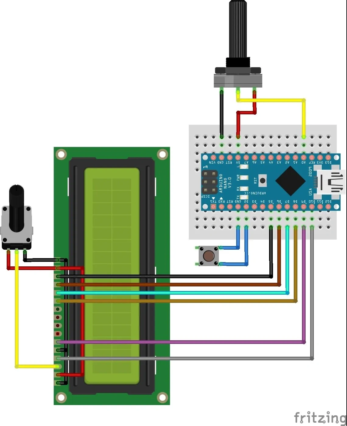
Arduino connection
Assembly instructions
To assemble CircuitMate, please follow the steps below:
- Printed parts:Print all the necessary parts using the provided STL files.
- Prepare the knob labelsPrint the knob labels from the PDF file and attach them to the upper part using tape or glue.
- Insert the heat-fused nut:Insert the heat-fused nut into the base
- Assembly of components:
- Connect the button to the base part.
- Install the potentiometer in the upper part.
- Put the breadboard into the base and make sure the USB connector of the Arduino can be accessed from the side slot.
- Install the knob:Fix the knob to the potentiometer.
- Optional - bridge connector at the bottom of the potentiometerIf necessary, use the bridge at the bottom of the potentiometer to bridge any gap between the potentiometer and the button.
- Electrical connection: Connect the Arduino Nano, LCD, and other components according to the provided diagram.
- Final assembly:Connect the upper part and the LCD to the base.
- Download the firmware:FromCircuitMate GitHub repositoryDownload the Arduino project.
- Calibration knob:Calibrate the knob value according to the instructions in the README file of the repository.
- Enjoy it:Your CircuitMate is now ready to use. Have fun!
Important noticeWhen installing the knob, make sure that the arrow on the knob is aligned with the starting point of the first label


 0
0 0
0 0
0

