BLE Gamepad
sarah35

Найти похожую с ИИ


Профиль печати(0)
Файл модели(0)
 0
0 0
0 0
0
Опубликовано:2016-05-29 19:07:51
0
0
 000
000BLE based gamepad. Like every other project in my life, it's in development (mainly the software at this point). It's a SCAD file, so it's pretty easy to modify (add/change axis button layout).
Note: The joystick holes look like they will not be holes, I assure you they will be holes when they are printed.
Parts:
1x Adafruit Feather 32u4 Bluefruit LE
1x LiPo Battery
1x Colorful Round Tactile Button Pack
1x Power Switch
4x 4-40 by 14mm Screws (Hardware Store)
2x Adafruit Joystick
OR
2x Sparkfun Joystick Breakout
2x Sparkfun Joystick
The Sparkfun joystick breakouts are smaller, but the gamepad was actually designed for the Adafruit breakout...I somehow only ordered one of these, and I couldn't bring myself to spend $30 on shipping for a single joystick shield...but either will work.
The Feather is really nice since it comes with built in battery management. I'm tempted to replace the BLE feather with a standard feather and use one of these cheap modules. The pros of this include being able to send arbitrary serial data. The cons include not being able to set the device as a HID joystick. To be honest, I hate USB HID. My only experience with it is writing a cross-platform joystick library. I would really prefer a serial port based gamepad system. But I'm trying to be hip and use this whole new "publish/subscribe" system...
Printer Brand:
MakerBot
Printer:
MakerBot Replicator 2X
Rafts:
No
Supports:
No
Resolution:
0.2
Infill:
10%
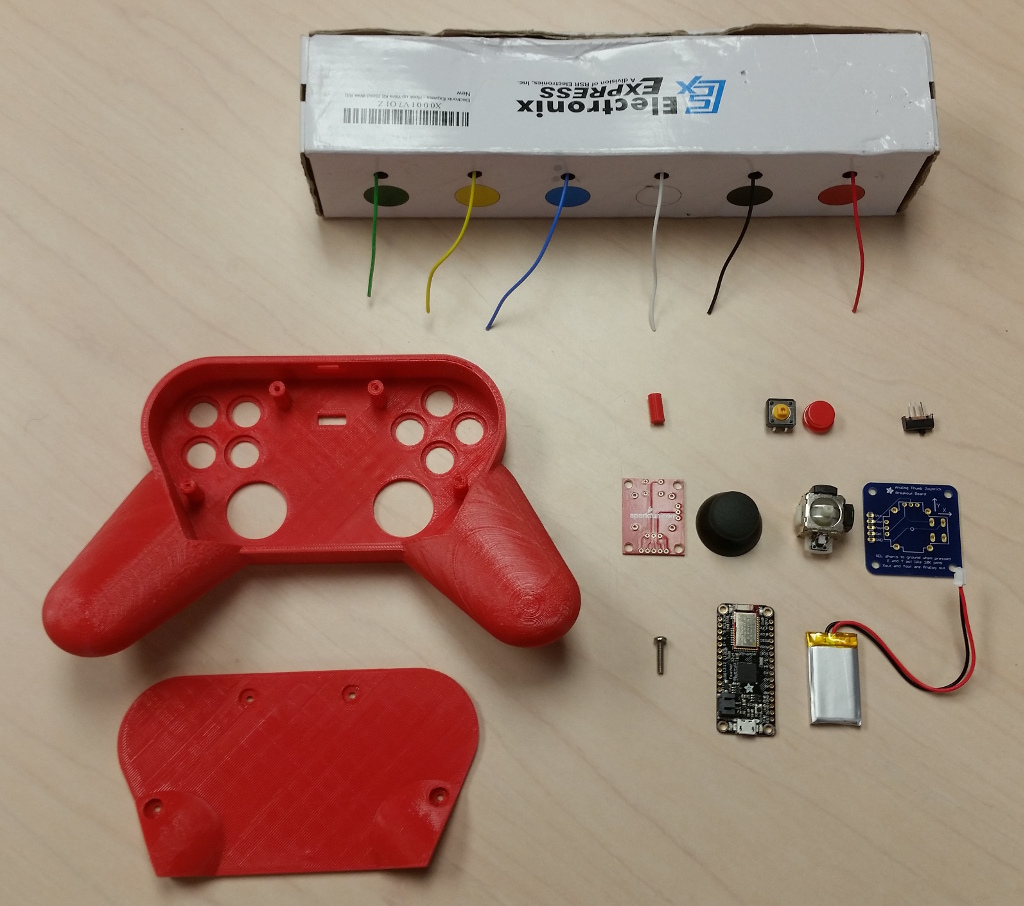
Be sure to grab all the parts in the Summary tab.
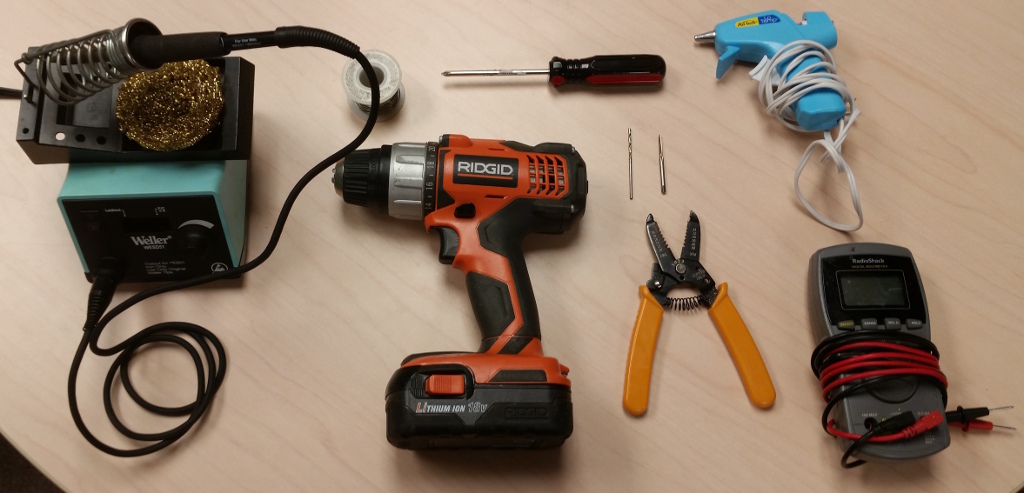
Soldering Iron
Solder
Drill
Wire Strippers
Multimeter
Hot Glue Gun
4-40 Drill
4-40 Tap
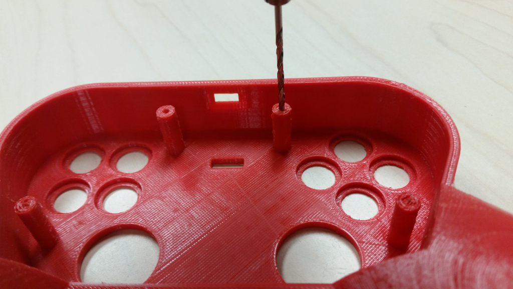
Drill out the screws holes with the 4-40 drill bit.
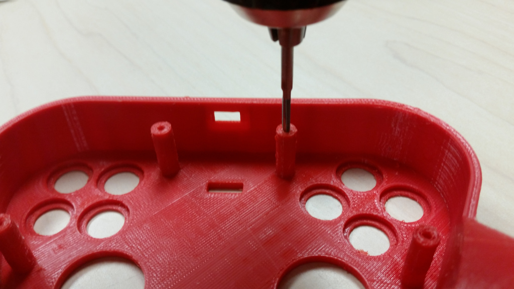
Tap the screws holes with the 4-40 tap. Do this slow, and remember that you're making threads here, so back out the bit.
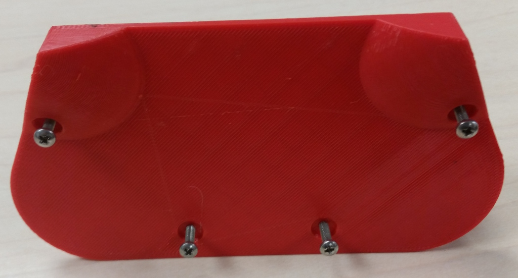
You can drill and tap the back plate screw holes if you wish, or over drill them such that the screws just fall through. Either way works!
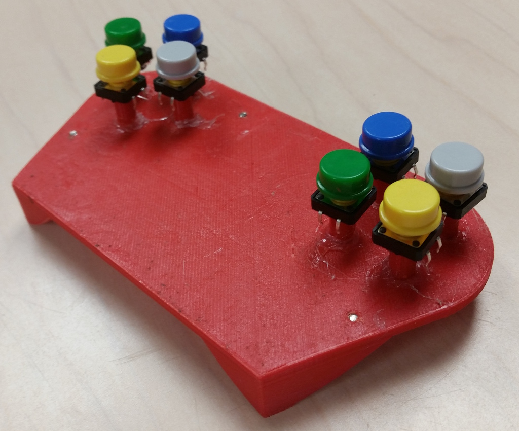
I'm not 100% happy with this system...but it works... Glue the columns to the back plate and then the buttons to the columns. Slow and steady here. I experimented with the directions of the buttons, I prefer the style on the left side of the picture above. The right side works, but you need extra wire between each of the buttons. I ended up changing the right side to match the left side.
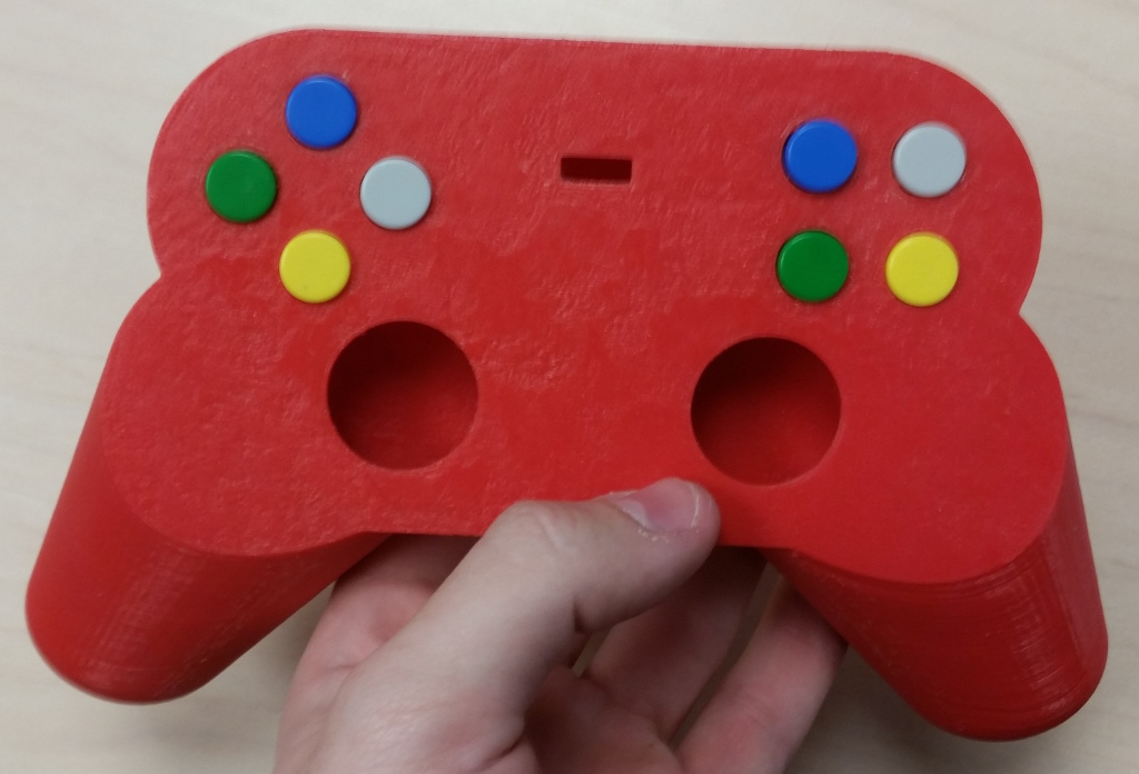
Before moving on, put the top plate on and make sure they still click.

Glue on the Feather. That's a terrible picture...if only I could retake it...
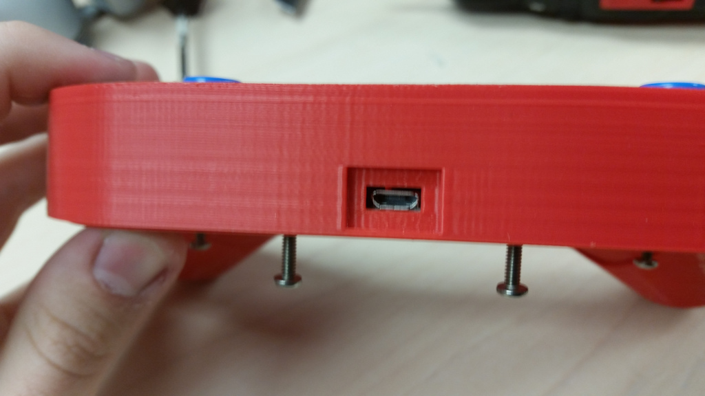
Before moving on, make sure the USB lines up with the hole on the top piece.
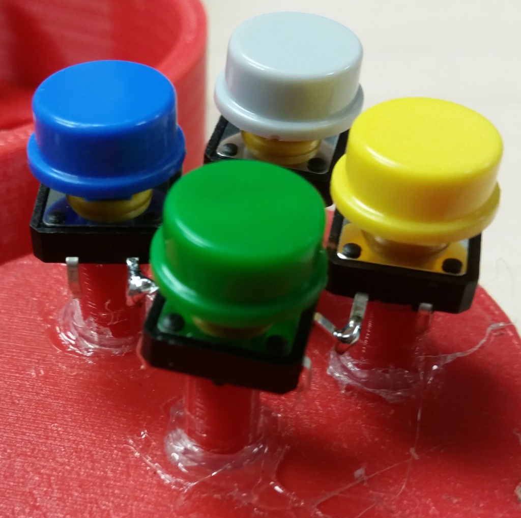
Start with the buttons. Bend the inner legs in a ring like so. Solder them together.
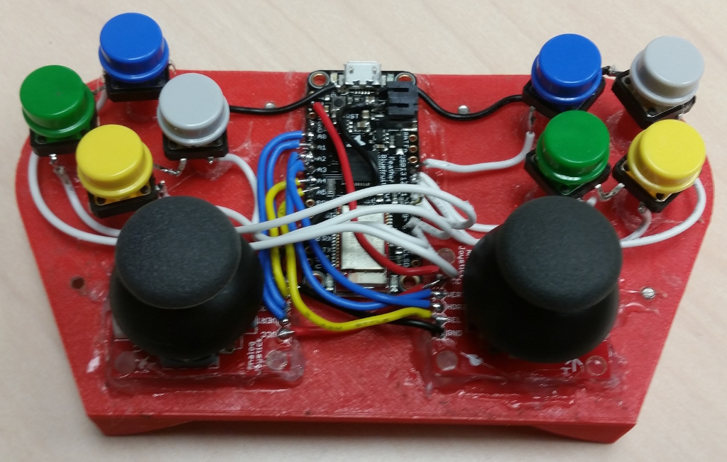
Glue down your joysticks (the Adafruit ones go directly on the corners, the Sparkfun ones you'll have to eyeball. Now for the soldering. I started with the with the joysticks (blue and yellow wires). Then the buttons (white wires). There's only one ground and power, but you can get three more ground from the sides of the USB connector and the battery connector.
FUTURE WIRE DIAGRAM HERE
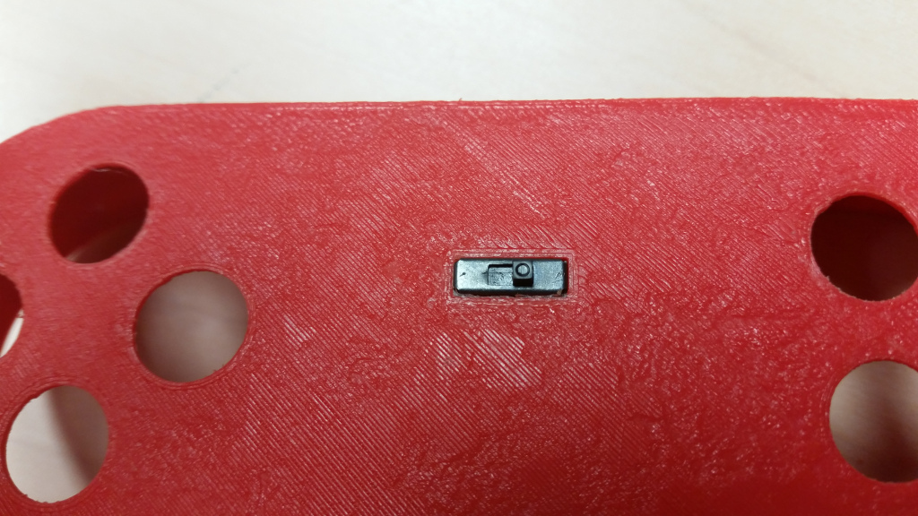
The last thing to put on is the power switch and battery (in that exact order). Fit the switch in the top plate.
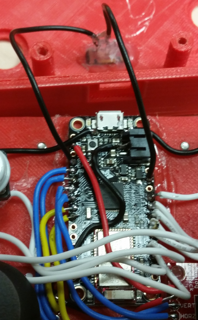
Solder the switch to ground and EN, and then hot glue it in.
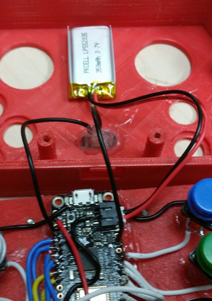
Hot glue the battery onto the top plate. Plug it in. I'd recommend testing the electronics as you go.
Before closing up, upload the testing firmware. This will spit out the joysticks and buttons to the the Arduino serial monitor. Test all of the axes and buttons before closing up.
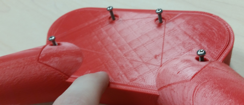
Screw the back plate onto the top plate.
In progress...