Leveling Fixture Light
griffin5177

AI로 유사한 모델 찾기


프로필 출력(0)
모델 파일(0)
 0
0 0
0 0
0
게시일:2026-05-15 02:21:26
0
0
 000
000This is a light and mirror for an F-35 leveling fixture. The bubble level on the fixture is difficult to view from above or with a mirror and flashlight so this device sits on top of the bubble level.
You can build one yourself with the models and instructions below, or email me to order one already built: mike@subtle-3d.com
Disclaimer: The object in these files are not officially endorsed or approved by Lockheed. It is considered Local Manufacture or Local Procurement. You will need to get approval from your unit to use it on an F-35 Leveling Fixture.
Features:
Consistent lighting to eliminate shadows, reducing visual error and increasing ease of use.
Mirror positioned at the optimal angle to view bubble position, also reducing visual error and increasing ease of use.
Mirror is optional and can be removed. A standard 2" inspection mirror should also fit in the mirror slot.
AA battery powered, no need to charge it if it's been sitting too long.
Off the shelf parts (Amazon).
Inexpensive.
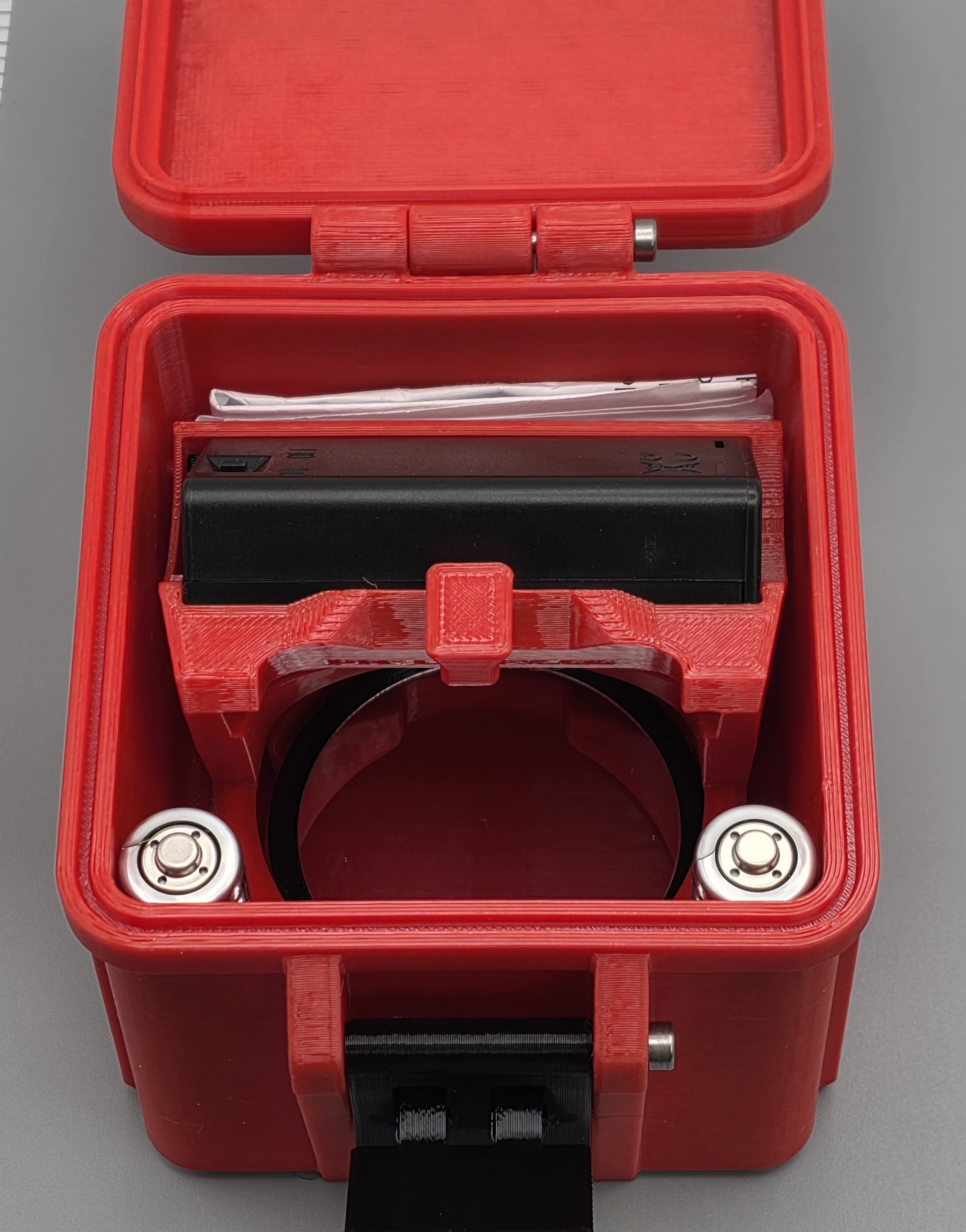
Storage Box keeps it secure.
Storage Box also has spots designed to contain 2 spare AA batteries, the round Mirror if an inspection mirror is preferred, and a spot for documentation.
There is also a PDF attached with the BOM and Printing Recommendations.
BOM | Amount needed | Link | Notes |
LED Filament, 255mm, 6500K Bright White (or equivalent) | 1 | https://www.amazon.com/dp/B0DGQ17CBN?ref=fed_asin_title&th=1 | You can also use any color you want. |
(alternate part) LED Filament, 300mm, 6500K Bright White | https://www.amazon.com/dp/B0DP4JHS8T?ref=fed_asin_title&th=1 | ||
Battery Box | 1 | https://www.amazon.com/dp/B0CSFFDN56?ref=fed_asin_title&th=1 | |
Mirror, 2" Round | 1 | https://www.amazon.com/dp/B0DP4JHS8T?ref=fed_asin_title&th=1 | Optional. Can use a standard 2" Inspection Mirror if desired. |
Screws #6-5/8" Wood | 2 | https://www.amazon.com/dp/B0DCVJJT1F?ref=fed_asin_title&th=1 | |
M3x40mm Hex Socket Head Cap Bolt | 3 | https://www.amazon.com/dp/B0DJQGWR1Z?ref=emc_p_m_5_i_atc&th=1 | |
AA batteries (Lithium type recommended) | 2 | Lithium AA's are highly recommended, alkalines seem to like to leak when sparsely used. | |
Heat Shrink | For the solder connections to prevent shorting. |
Printing recommendations:
Printed Parts | Version# | Recommended Material | Recommended Color | Recommended Printer settings |
PLA not recommended. PETG or better. | Parts can be any color but the diffuser needs to be transparent. | Standard 0.20mm Layer height settings with changes below | ||
Light Body | V6 | PETG | Red | 4 Perimeters/Walls |
Light Diffuser | V3 | PETG | Transparent Req. | 4 Perimeters/Walls, Print Hot for better transparency, ~270C |
Light Retainer | V4 | PETG | Black | Default Settings |
Mirror Body | V2 | PETG | Black | Default Settings |
Container Bottom | V4 | PETG | Red | 4 Perimeters/Walls |
Container Lid | V3 | PETG | Red | 4 Perimeters/Walls |
Container Latch | V1 | PETG | Black | 4 Perimeters/Walls |
Build Instructions:
Soldering will be required to connect the LED filament to the Battery Box.
Order the components
Print the parts
Slide some Heat Shrink material onto the wires.
Solder the LED filament to the Battery Box wires. Be sure to have the polarity correct. The + end of the LED filament has a small hole in the end and will be soldered to the red + wire on the Battery Box.
Heat the Heat Shrink around the solder points.
Tie a knot in the Battery Box wires. This prevents wire/LED removal/brakeage when unclipping the Battery Box to change the batteries.

Gently thread the LED through the Light Body.
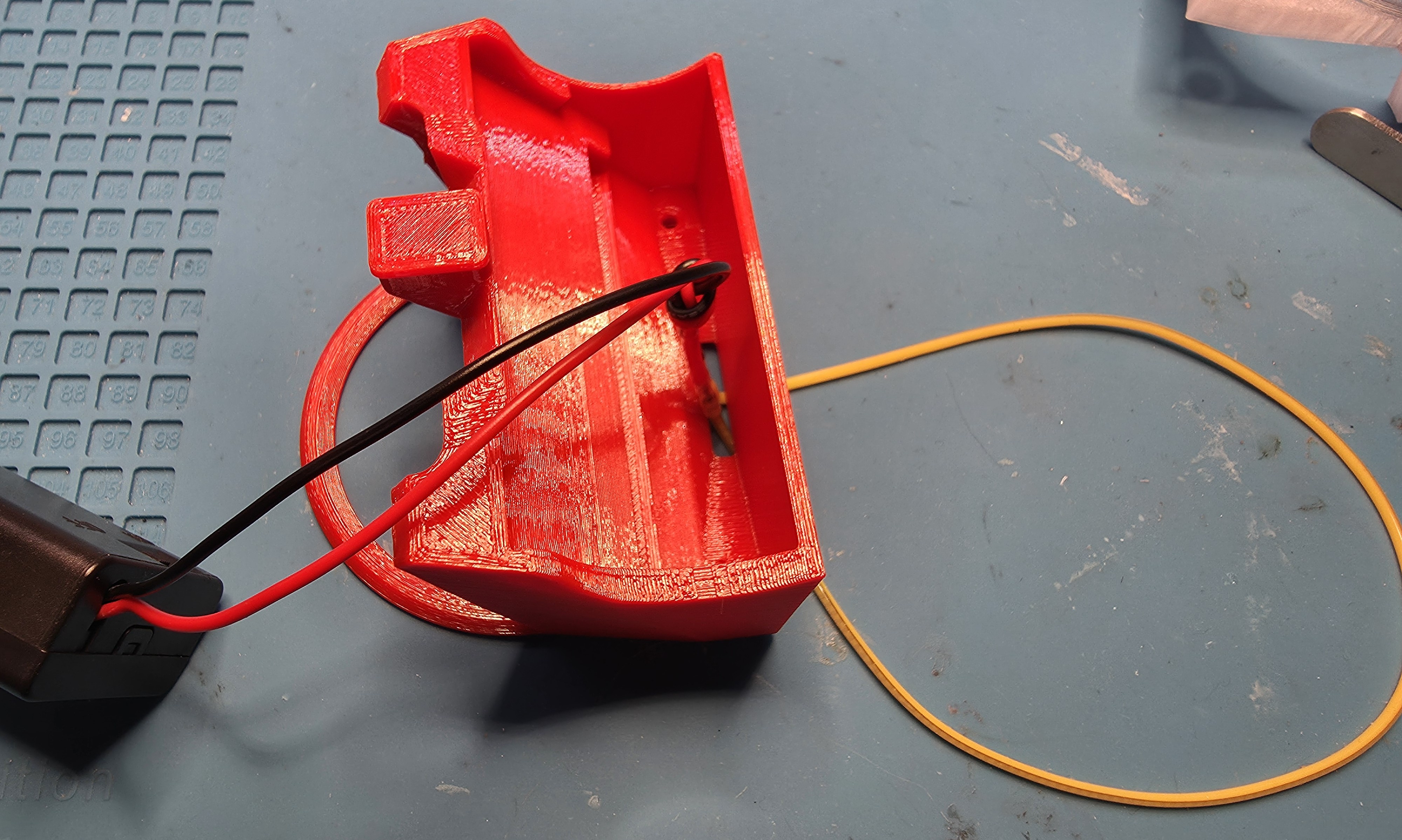
Position LED filament in the diffuser like this.
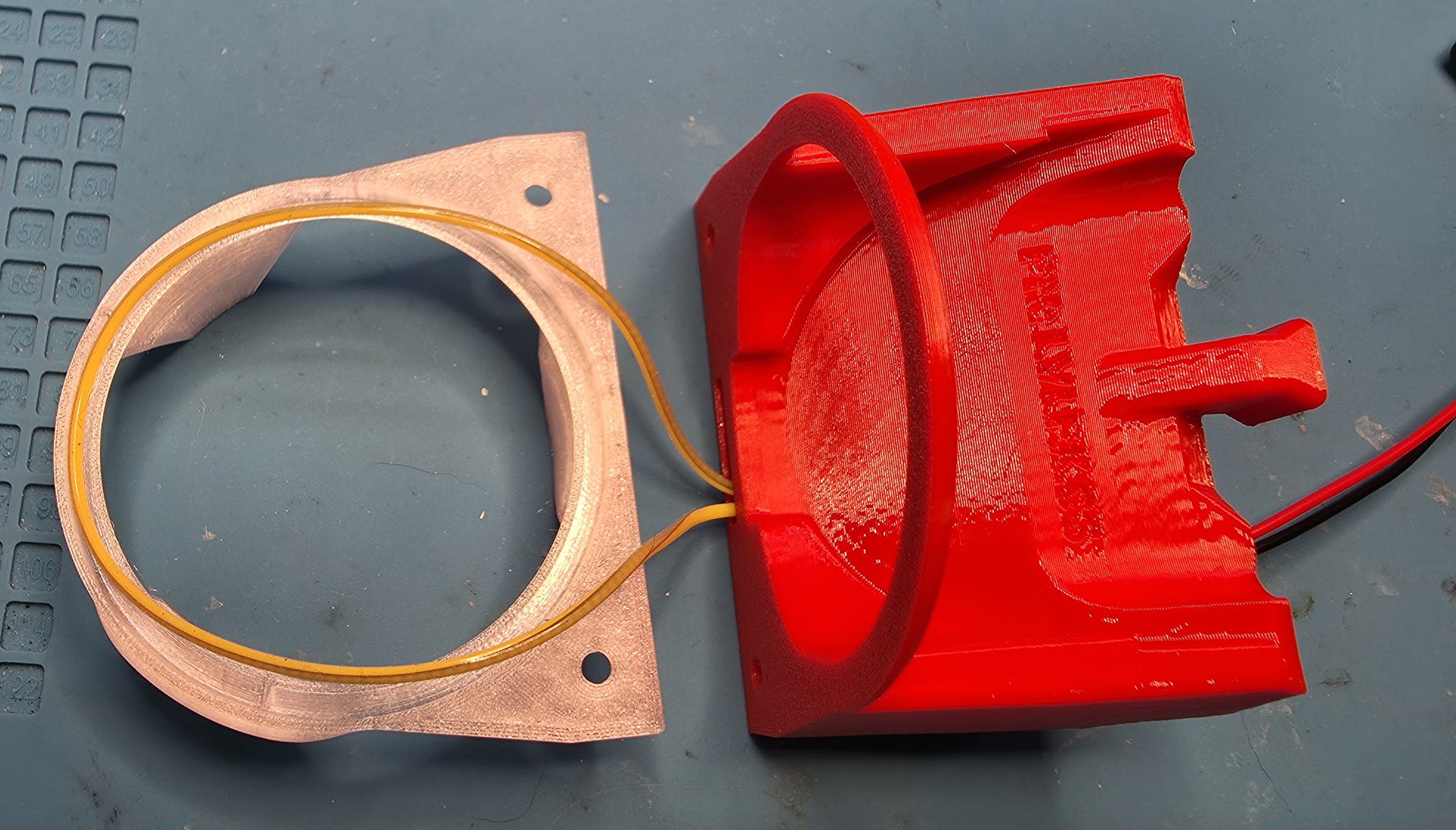
Gently place the Light Body on the Diffuser. Be careful not to pinch the LED filament. It should be sitting in the diffuser groove and up through the Light Body hole.
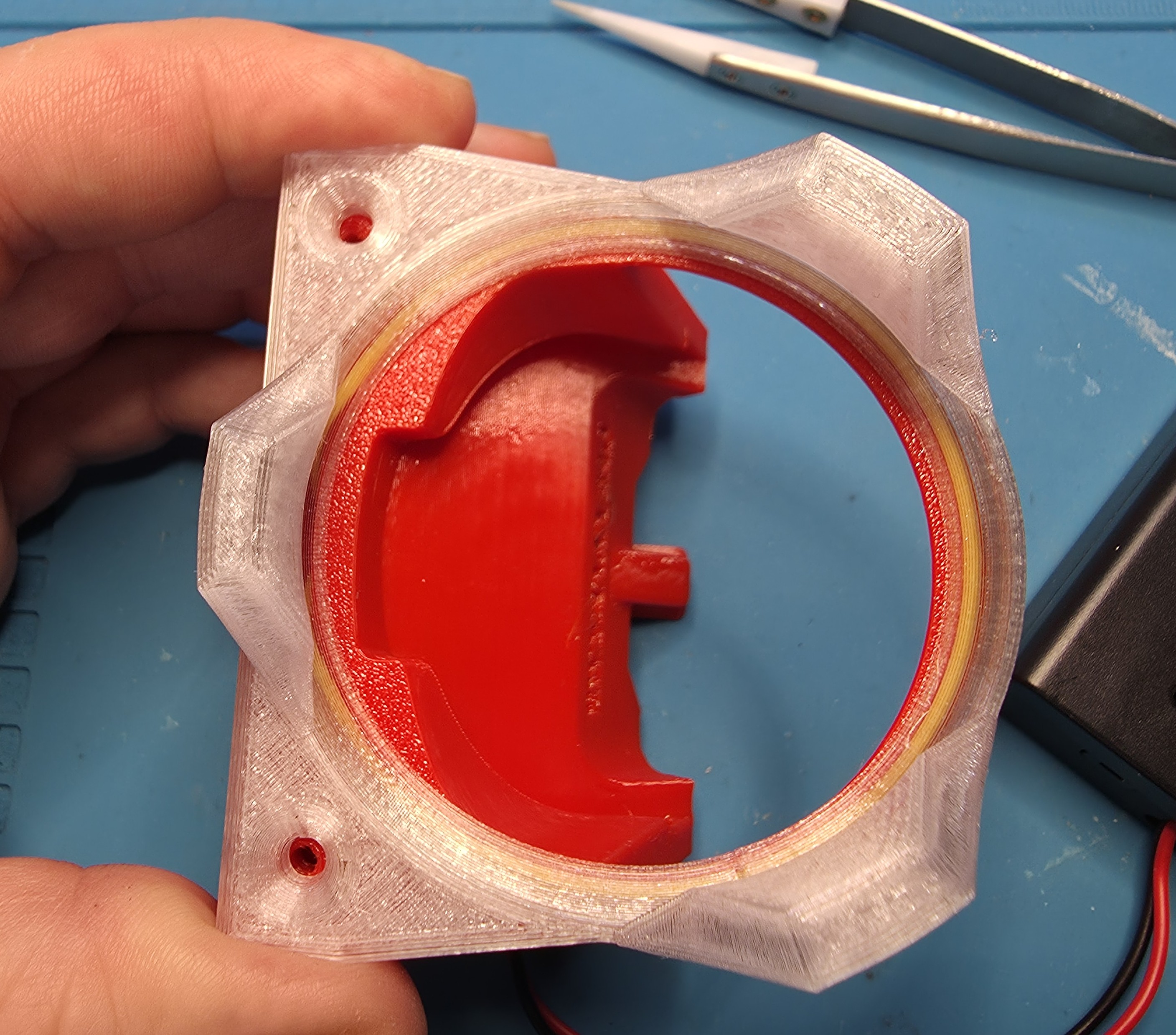
Hold the Body and Diffuser together and route the wires like this, with the knot inside and keeping everything clear of the screw holes and front lip on the Body.
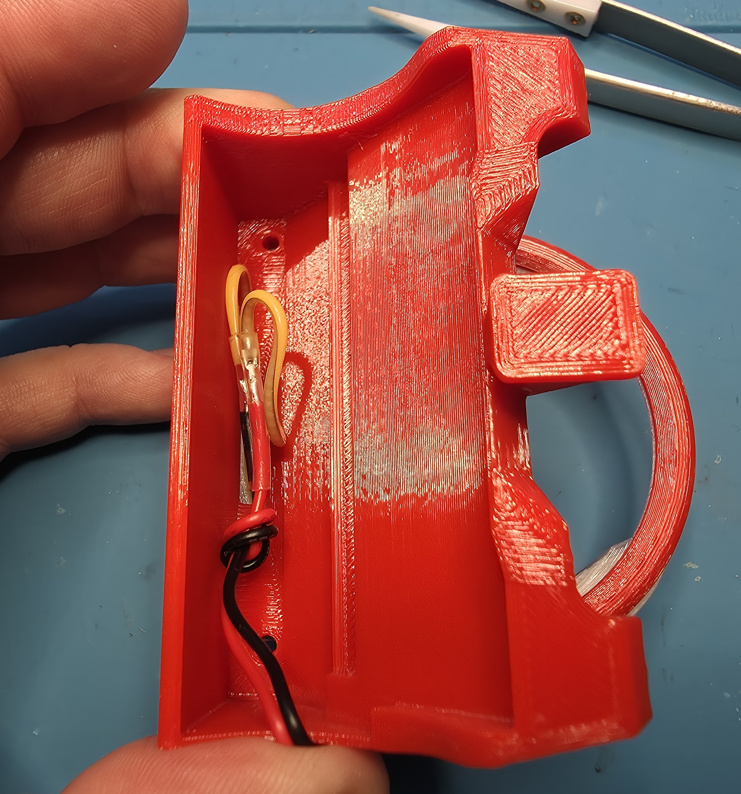
Place the Inner Cover over the wires and press it down. Be careful not to pinch the wires.
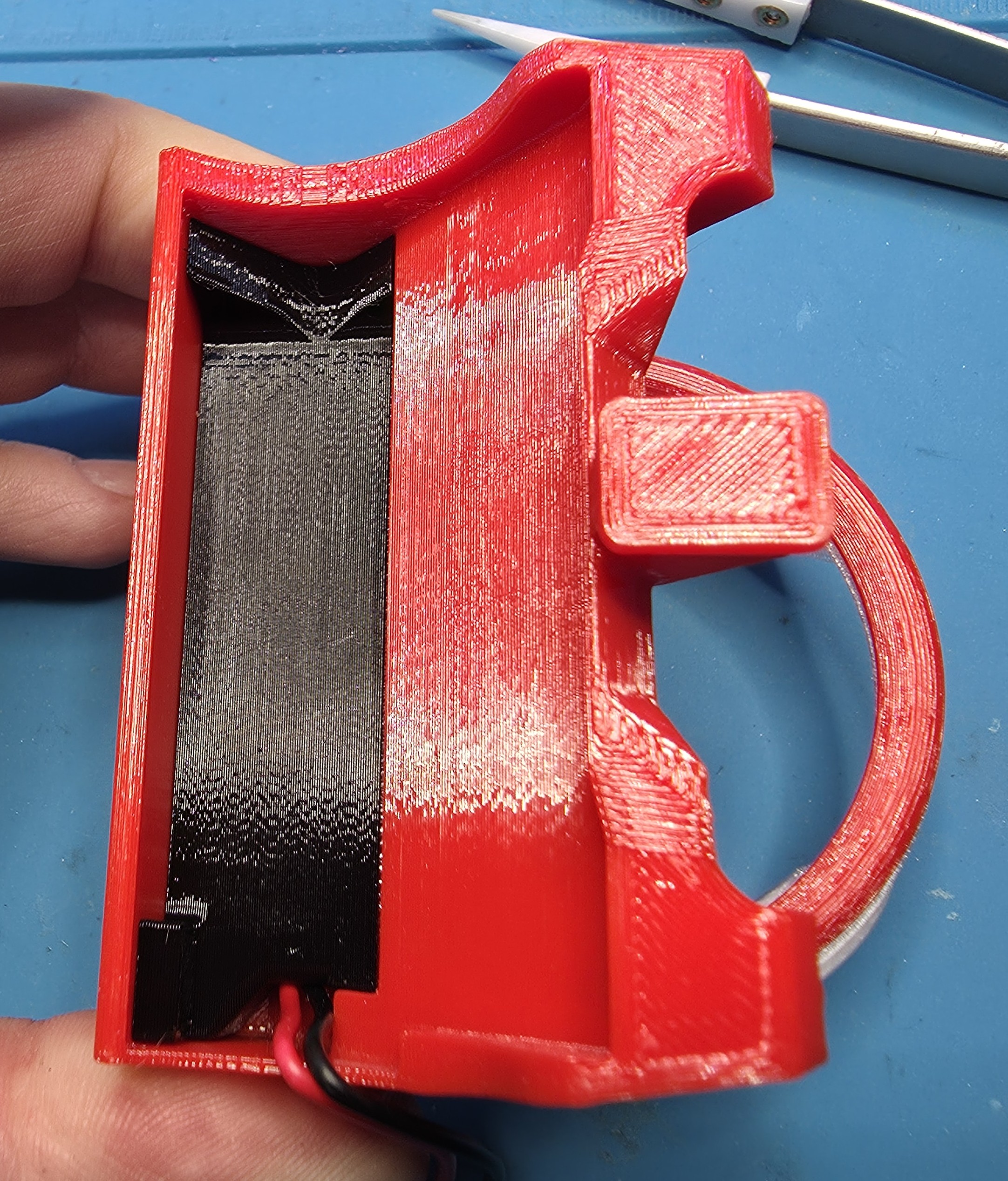
Hold the parts together and insert the screws. They will go through the Diffuser the Body and screw into the Inner Cover.
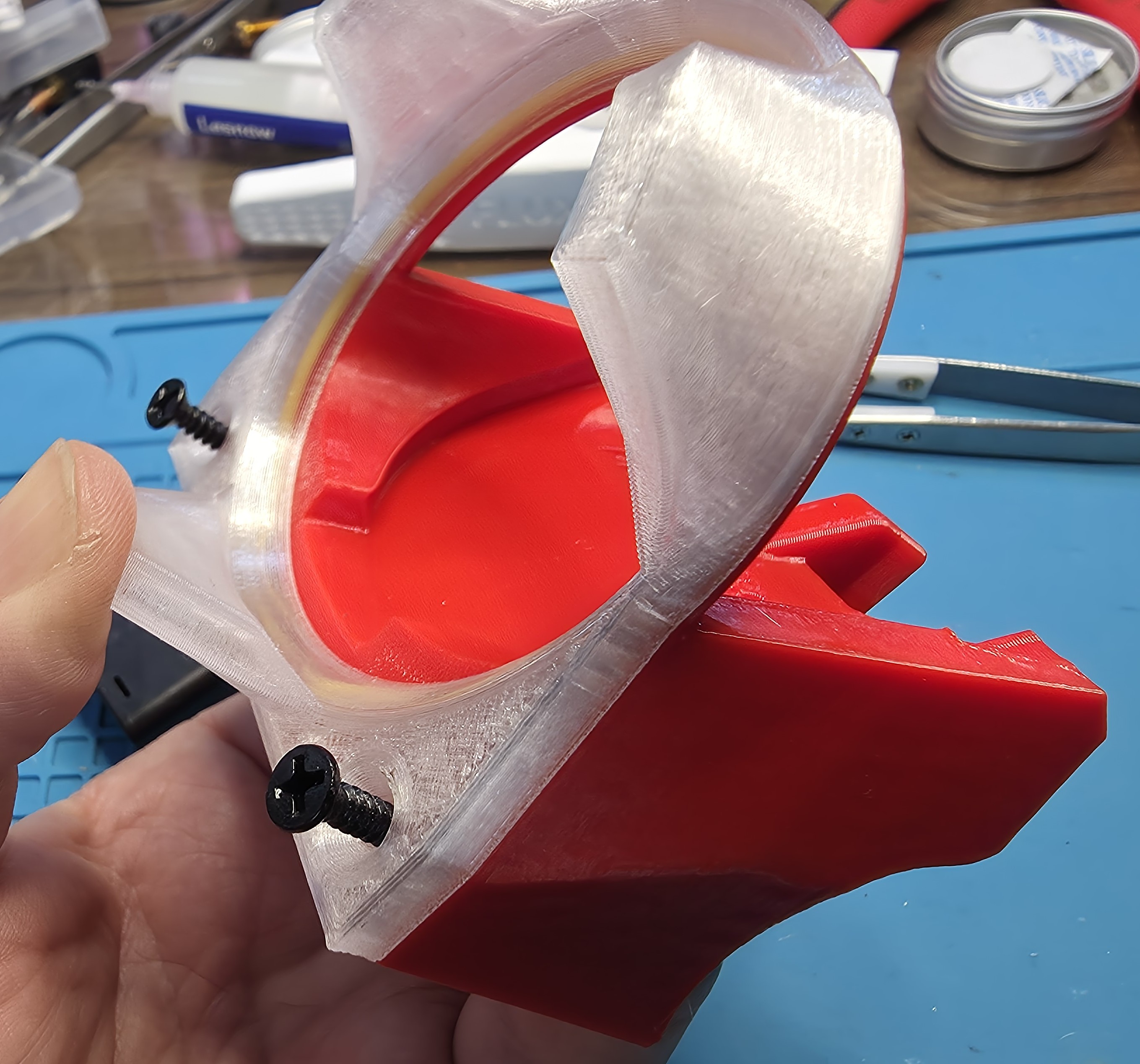
Insert Batteries test and install battery cover.

Fold and route the wires like this, keeping clear of the outer sides.
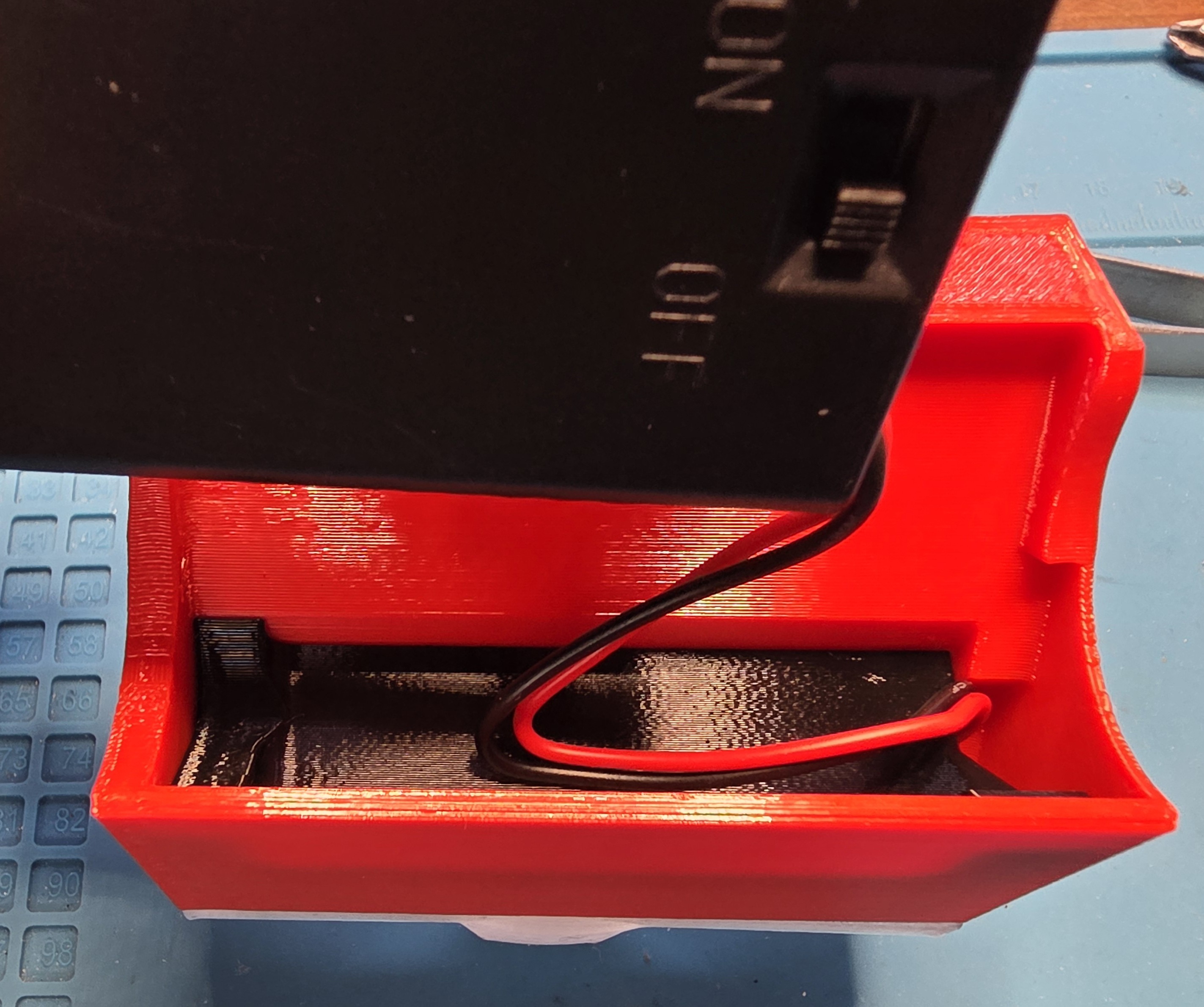
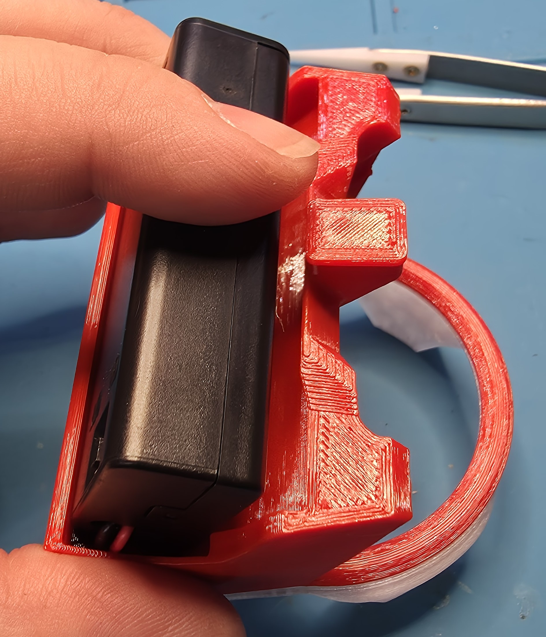
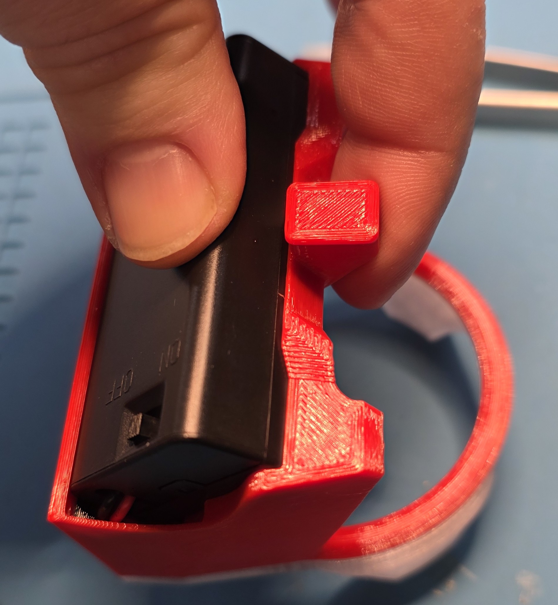
Place the Battery Box in the Body, again, making sure not to pinch wiring, and it should easily and securely clip into the Body. If it takes a lot of force then there is likely a pinched wire somewhere.
Install one 40mm bolt into the Box Body and Latch until the end of the bolt is flush with the plastic. Do not overtighten.
Install two 40mm bolts into the Box Body and Box Lid until the end of the bolt is flush with the plastic. Do not overtighten.
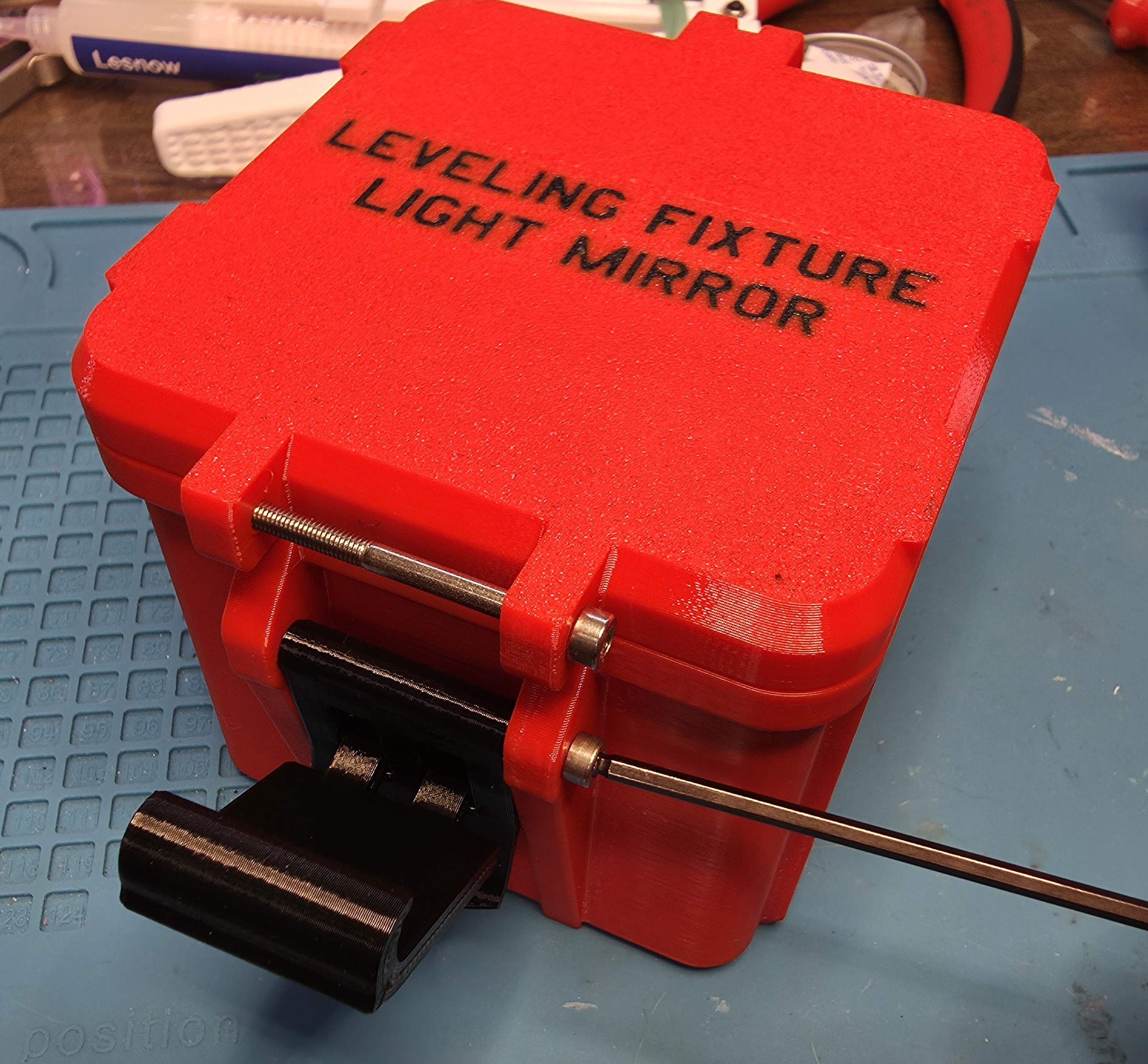
Done!