Advanced parametric drill bit sharpening jig (2/4 facets, conical, split point)
TidyPlate

AI로 유사한 모델 찾기


프로필 출력(0)
모델 파일(0)
 0
0 0
0 0
0
게시일:2026-01-25 06:34:57
0
0
 000
000It's always frustrating to accumulate dull drill bits: they are completely useless, but it would be annoying to throw a bit which would potentially be as good as new with a small amount of grinding.
However, properly sharpening a drill bit (especially small ones) is not straightforward. This design makes the task much easier, requiring only cheap, simple tools: a whetstone (diamond plate will be better suited for larger drill bits), and a diamond needle file if you want split point sharpening.
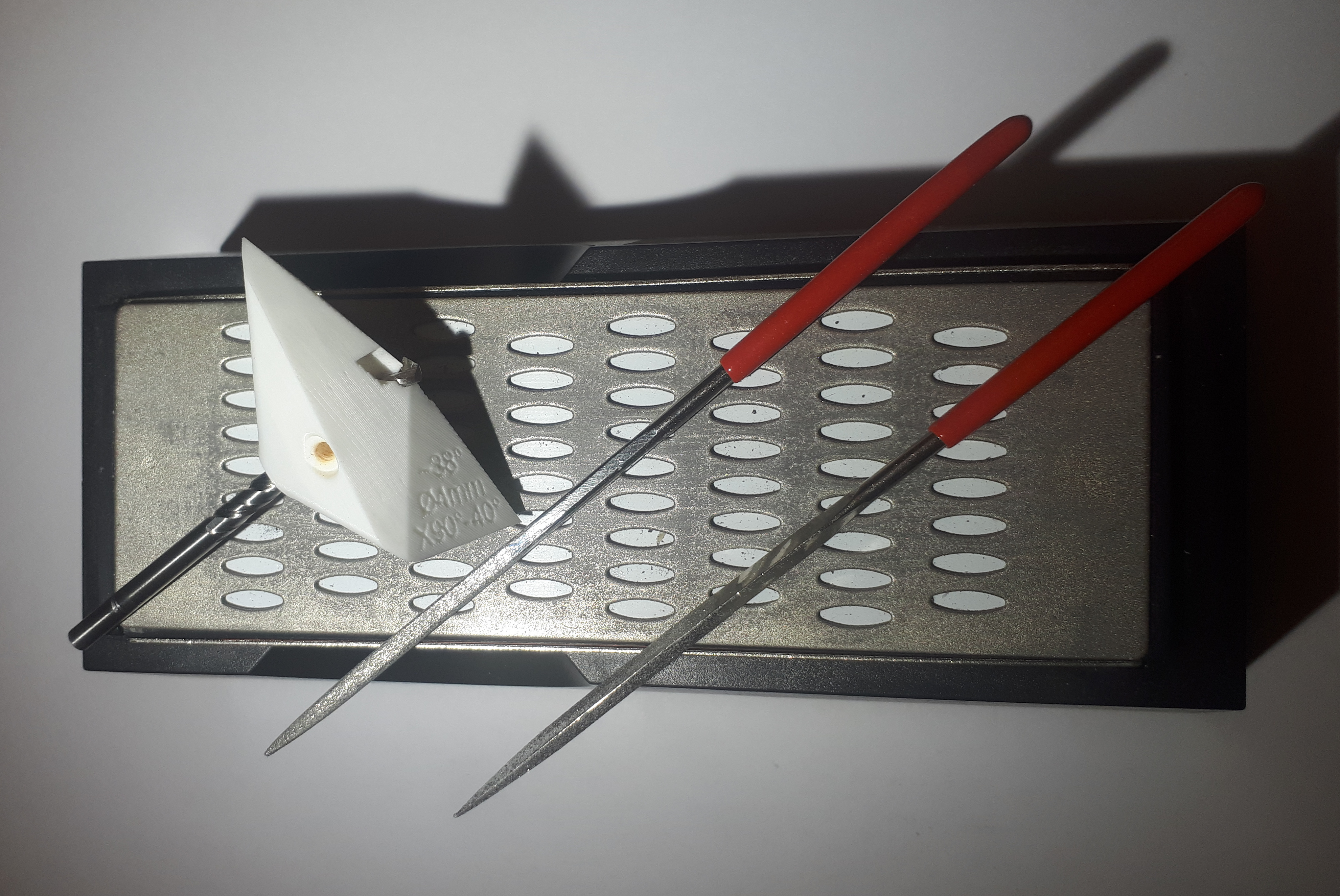
Other popular ways of sharpening drill bits use a grinding machine or rotary multi-tool with a guide to assist with point angle. The whetstone method has several benefits and may be better suited for small drill bits: better control of angles, centering, and more careful grinding. And it offers additional sharpening options, like 4-facets or conical sharpening, and point splitting.
I found two existing design based on the same idea: this one is also done with OpenSCAD and parametric. There is also this design which features a similar four-facets shape. The present model is more configurable than those, I included every parameter I could think of in the configuration options, and a key difference is that it also matches the drill bit flute (based on the helix angle) to ensure proper angular alignment. The downside is that it requires more customization work, and each jig can only match one drill bit (but it only takes about 5g of PLA).
This explains the customization process which needs to be performed for each particular drill bit, before printing. This is done in the OpenSCAD GUI. I have included some settings that I use as a (compressed) json file used by OpenSCAD, as well as some STL files an example, but you will still have to determine your own (at least helix angle and circumferential angle) as described below. The key parameters are embossed on the jig for easier identification.
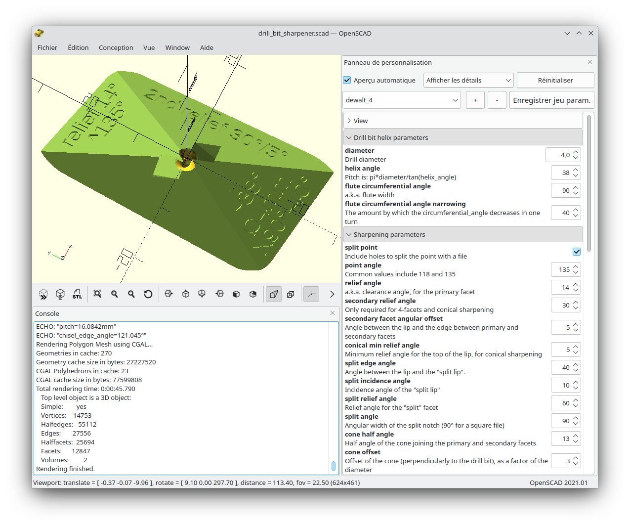
A distinguishing features of this model is that the drill bit hole comprises two helices which match the drill bit's flutes (grooves) with minimal play, to ensure proper angular positioning (i.e., lips alignment). This is important because rotating the drill bit by just a few degrees is equivalent to changing the relief angle by a few degrees (and the point angle to a more benign extent), which is significant.
To achieve this tight helix fit, the following parameters have to be set:
To determine the parameters (beyond diameter), you should first measure the helix pitch: the distance between two repetitions of the flute's cutting edge, and use the formula pitch=pi*diameter/tan(helix_angle).
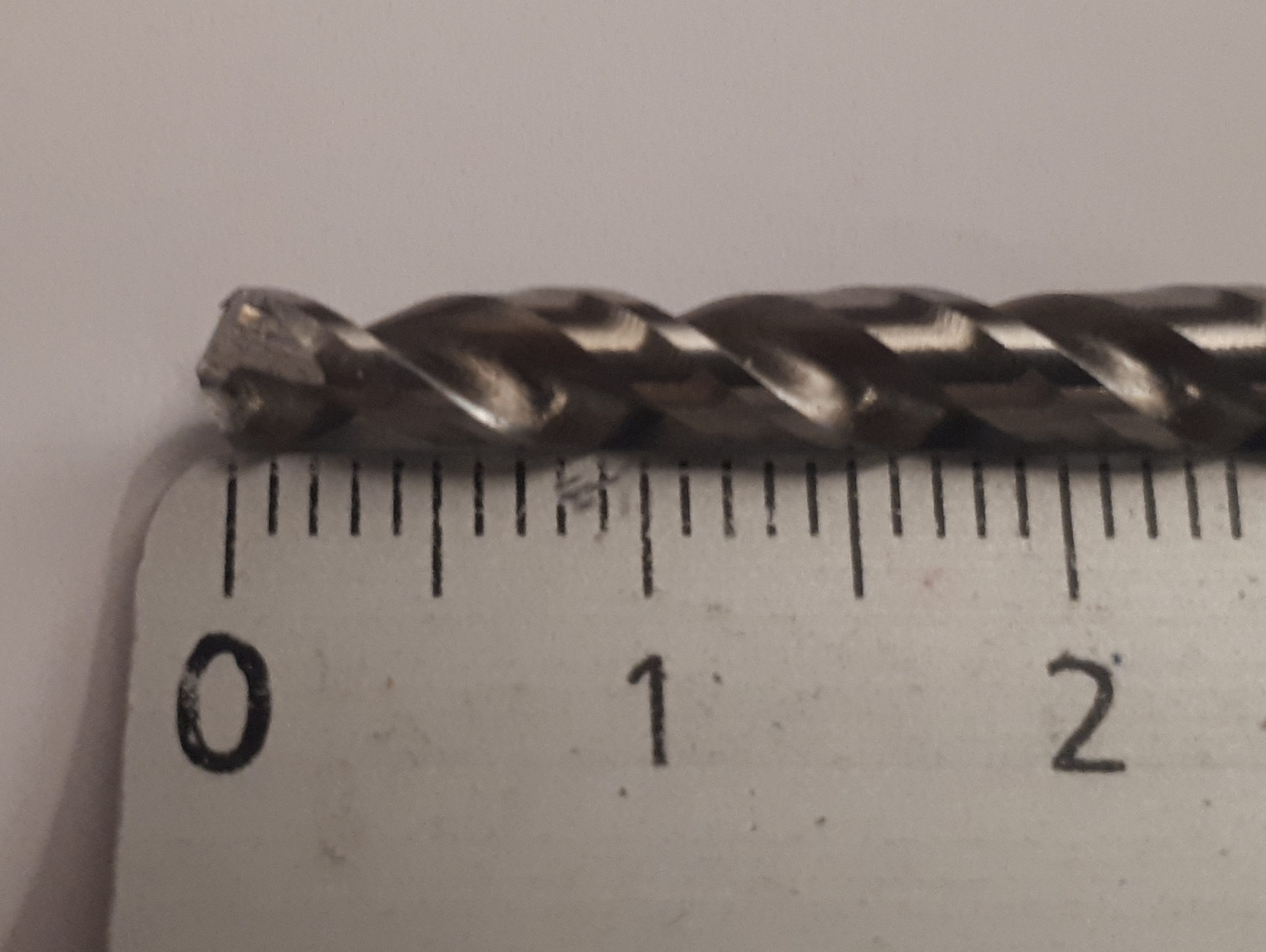
Example: The measured pitch in the above pitcure is 16mm.
Then, determine the flute circumferential angle by printing the profile test part and taking the minimal value for flute circumferential angle such that the drill bit's tip fits (tightly).

If the drill bit's tip fits in the profile test part but cannot be pushed further, then this means that the flute's depth and width decrease toward the shank. In this case, set flute circumferential angle narrowing to a positive value (e.g., 30°), set profile test turns to 1 or 2 (depending on the drill bit's body length) and re-print the profile test part. the angle narrowing value will be correct when the test part can be inserted up to this number of turns from the tip.
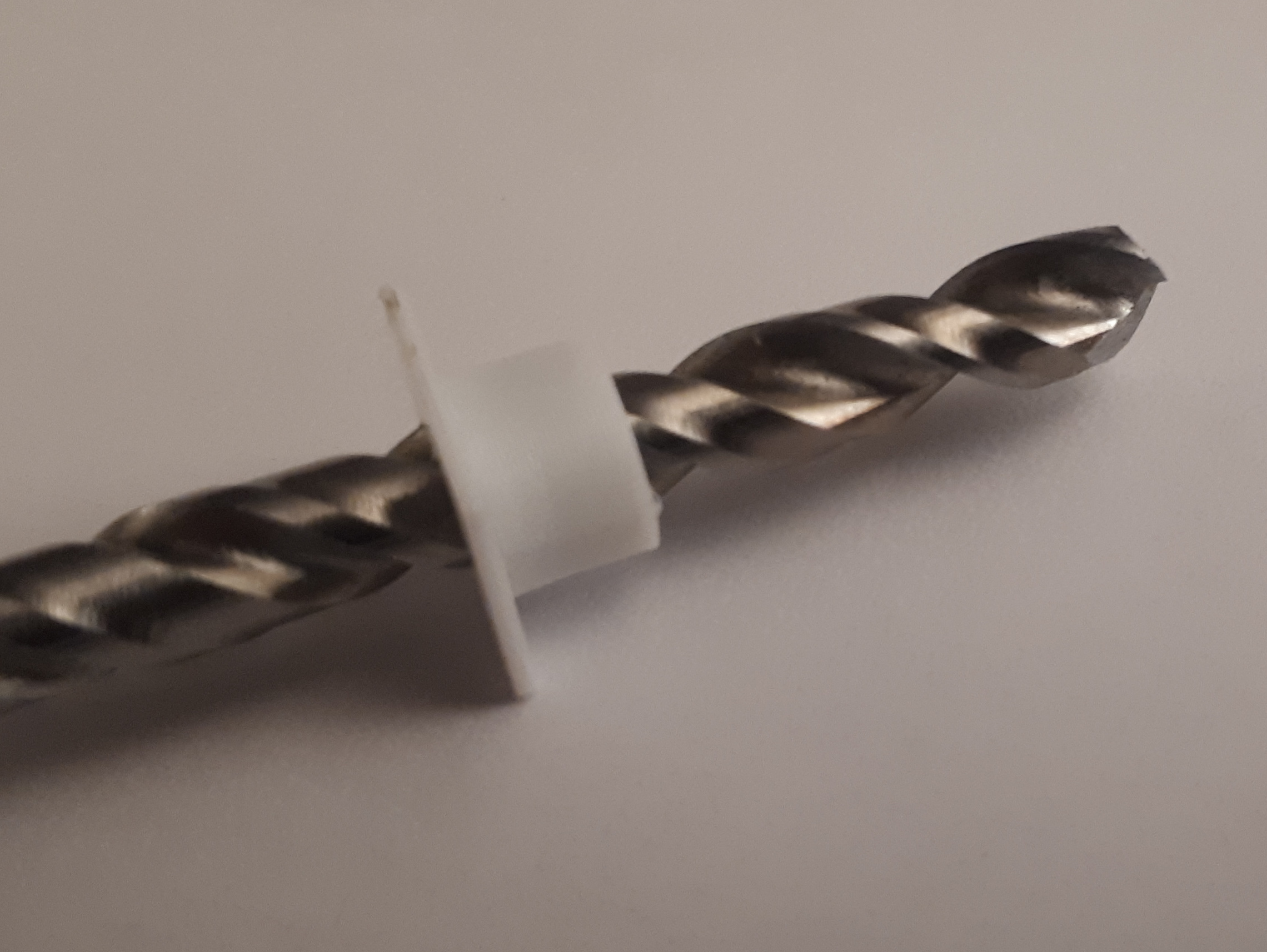
Example: profile test printed with profile test turns=1 and circumferential angle narrowing=40, blocked at 1 turn.
Finally, adjust the pitch measurement by inserting the two profile test parts (twice the same is flute circumferential angle narrowing is zero) with the square outline aligned and measuring more accurately the distance between the two.
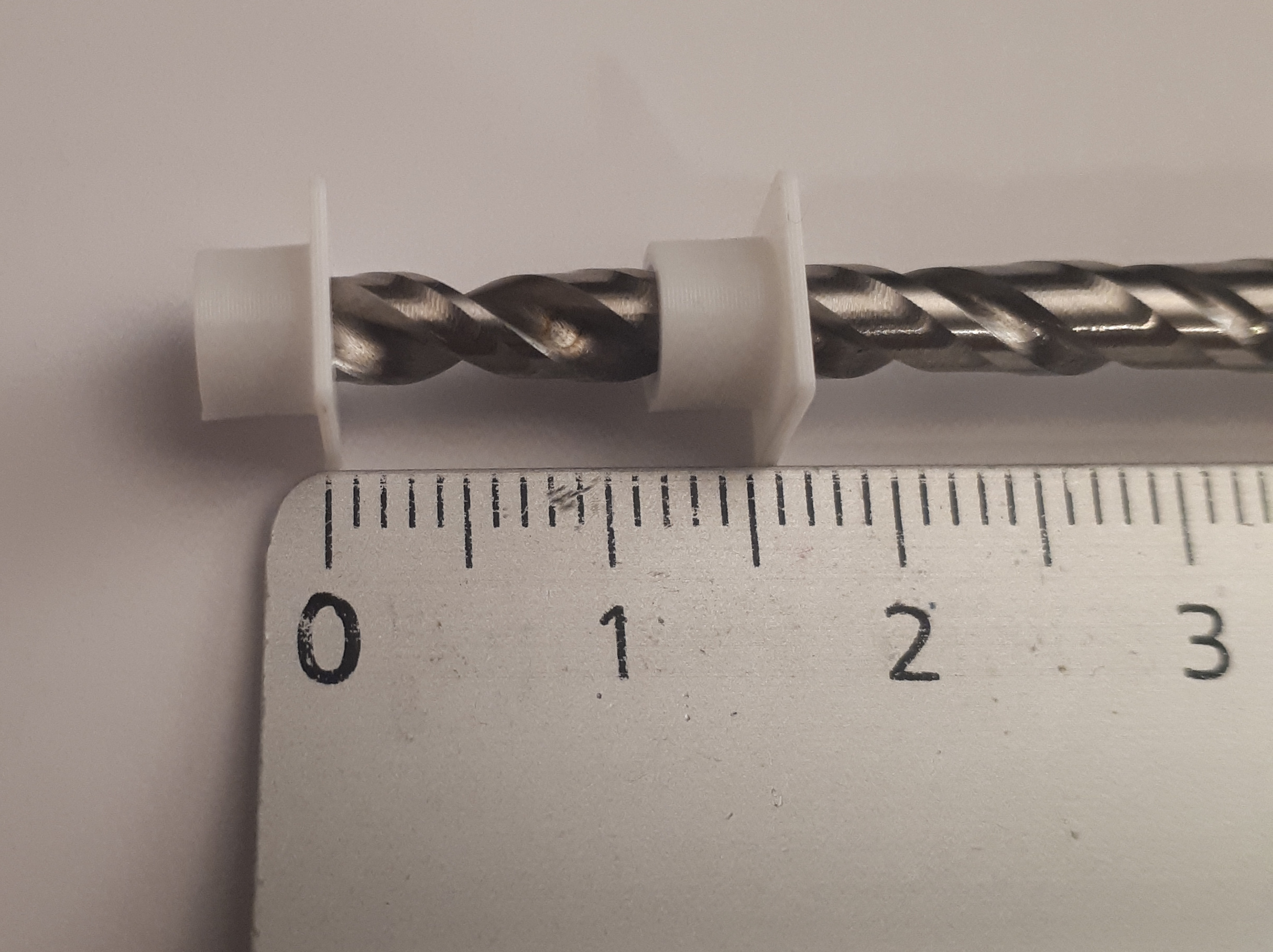
You can then print the facets test part to check that the fit is correct ; this can also serve as a rough check for point angle.
The sharpening parameters are independent from the above drill bit parameters. You can choose arbitrarily the point angle (though it may require significant grinding to change a drill bit's current point angle), and the sharpening style.
Three different jigs can be printed, each corresponding to a different sharpening style. In addition, for each sharpening style you can enable split point, which will add notches for guiding a square or triangular needle file for point splitting. The base sharpening styles are:
You can preview the effect of different sharpening style by setting part to the corresponding drill bit model: two facets drill bit, four facets drill bit, or conical drill bit.

two facets |

four facets |
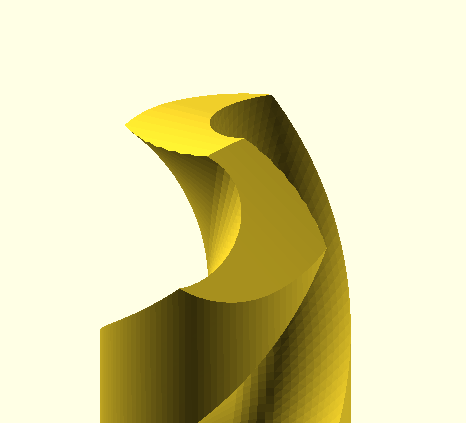
conical |
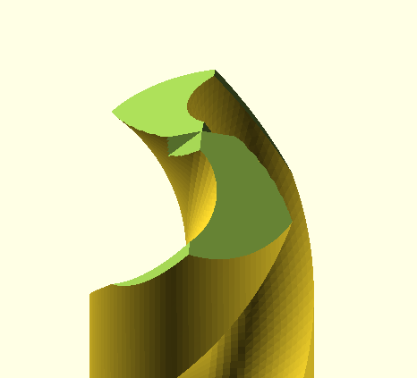
two facets, split point |

four facets, split point |
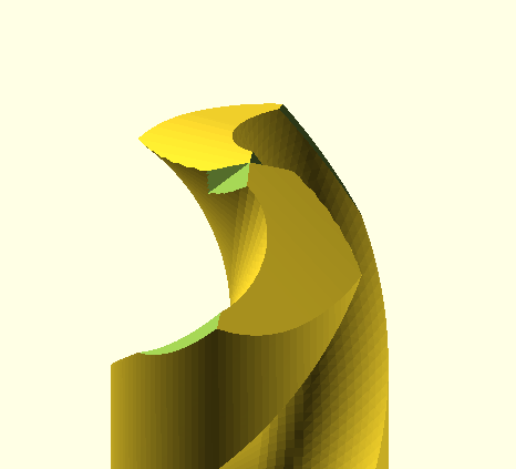
conical, split point |
Only two parameters define the facets orientation in two-facets sharpening:
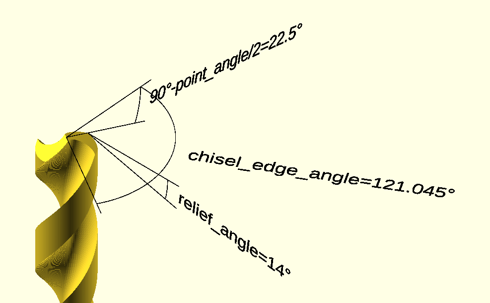
There is a subtlety in the definition of those two angles: because the center of a drill bit has some thickness (web thickness), the lips do not meet at the center, but are inclined “backward” w.r.t. the drill bit's radius. The lip may not even be a straight segment, depending on the flute profile (and point angle). For this reason, I only considered the outer corner of the lip for the definition of point angle and relief angle. Defining them relative to the lip's edges would yield slightly different values, but this doesn't change the overall expressiveness.
Another standard definition is the chisel edge angle, which is the angle between the chisel edge and the lip (more precisely here, the segment between the tip and the lip's outer corner). It is related to the other angles by the formula:
tan(relief_angle)*tan(point_angle/2)=tan(chisel_edge_angle-90)
This can be used to estimate the relief angle from the point angle and chisel edge angle, though not very precisely.
Set part to two facets angles to see the illustration of those three angles' definition.
For four-facets sharpening, the primary facet is defined according to point angle and relief angle as in two-facets sharpening. The secondary facet is defined by two additional parameters:
For conical sharpening, point angle and relief angle determine the tangential surface at the lip's outer corner. The second relief angle parameter is used to “cut” the cone and extend it with a planar facet for the rear part (secondary facet angular offset is not used). This way, conical sharpening can be viewed as a slightly modified four facets sharpening where the edge between the primary and secondary facets is smoothed.
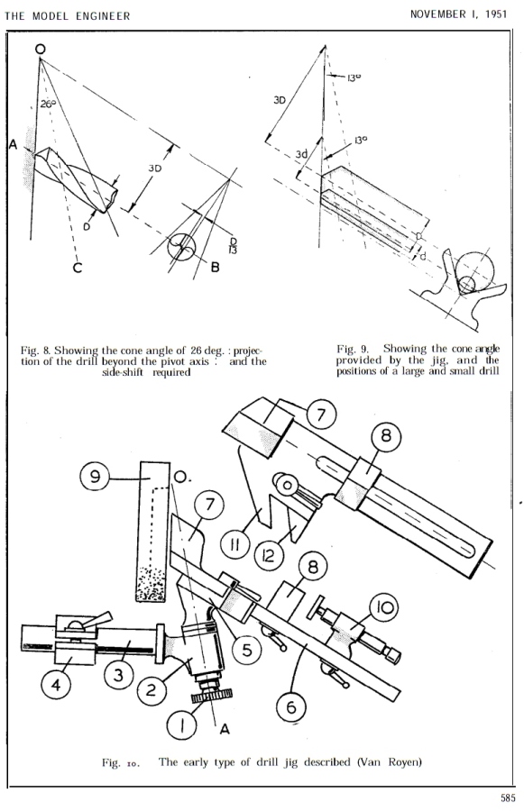
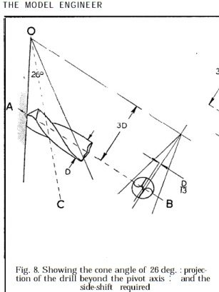
The additional cone parameters cone half angle and cone offset can be used to vary the shape further. Default values 13 and 3 correspond to the indications given in this illustration published in "Model Engineer" explaining conical sharpening. Here is the relevant part:
Finally, conical min relief angle acts as the opposite of second relief angle and determines how much the cone extends in front of the lip's outer corner, before being cut and extended with a planar facet.
In theory there is no need to “cut” the cone with conical min relief angle and second relief angle, but this is necessary to give some width to the sharpening jig, and also to have some flat surface to emboss the parameters. This also avoids unnecessary grinding at the rear.
The last sharpening option is point splitting, which significantly improves drilling performance. This requires a needle file (preferably a diamond one due to the hardness of HSS), square or triangular, but with a sharp edge. I had satisfactory results with cheap diamond needle files, though it takes some work, and the corner is not as sharp as what my drill bits originally looked like.
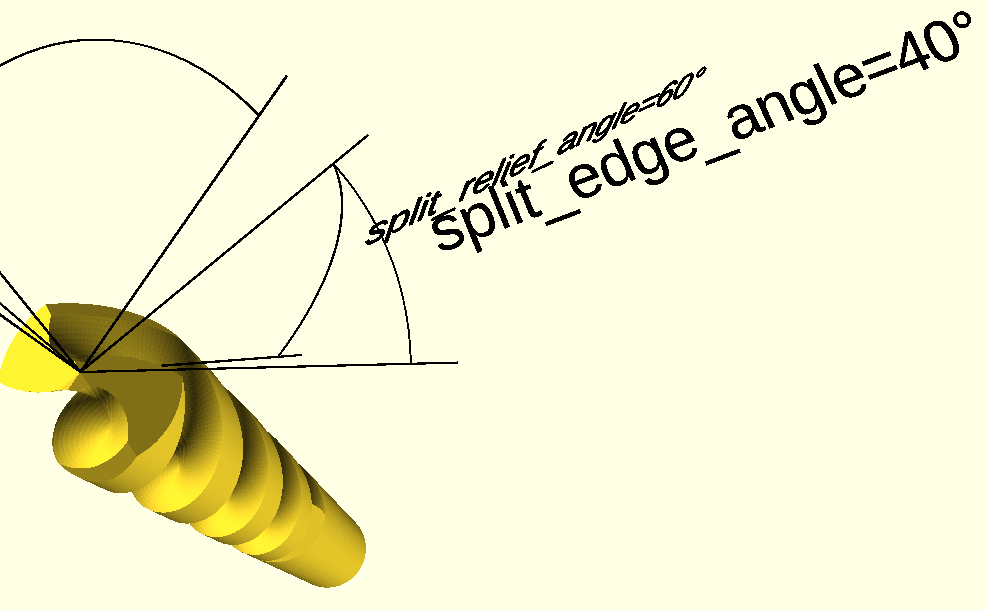
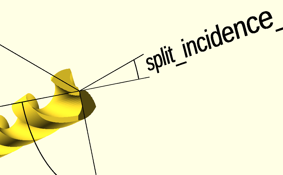
The notches that will guide the file are configured by four parameters:
Set part to split angles to see the illustration of the meaning of split relief angle, split incidence angle, and split edge angle.
|

|
|
|
Two screws are used to secure the drill bit in position. You can use small screws with a pointed tip, or “sharpen” two screws to make them pointed (a small handler is included to sharpen M2x10 screws). Adjust the parameters accordingly:
The remaining parameters allow you to change the sharpener's dimensions, text size and position, and a few miscellaneous features. They should be mostly self-explanatory.
All jigs can be printed easily in PLA without support. I used 0.15mm layer height, 0.8 outer thickness, and 15% infill. Any color other than white or translucent will be more readable.
Insert the drill bit so that the tip only shows by a few tenth of a millimeter beyond the faces, and secure it with screws.

If you want to split the point, it's best to do it before grinding the surface, for a better finish. Carefully file until the notches meet exactly at the tip.
The jig helps to obtain perfectly symmetric faces by centering the drill bit, though you may have some issues if your drill bits are no straight, which can happen with entry-level, laminated drill bits. I all cases, I suggest grinding by alternating frequently between the two sides, applying the same number of passes each time (and with the same pressure), to help keeping a symmetric shape.
It is advised to grind perpendicularly to the lip, and only “backward”, to avoid cutting you whetstone instead.
For four-facets sharpening, the primary facet requires the least grinding, so it can be a good idea to do it last, while frequently checking progress.
I have used those jigs to sharpen a few of my Dewalt "Extreme" and other drill bits, with success. Split-point sharpening in particular gives good results, and I have been able to apply it to bits as small as 2mm in diameter. Detailed pictures show that even the four-facets sharpening can be done precisely. After a few experiments, I think that conical sharpening jig is a great choice (together with point splitting): I had good-looking results with little effort. The process is almost identical to two-facet sharpening, with just a little twist added to the grinding gesture, and the output is definitely better.

Further development could include a more forgiving flute handling, to precisely center the tip of drill bits that are not perfectly straight. It would be nice also to have some way to accurately measure and reproduce the current sharpening angles on a drill bit.
I also have “pilot point” drill bits, featuring a smaller diameter tip sharpened in a “regular way” (135°, split point) and a nearly flat sharpening of the outer helix a few millimeters below. A nice addition would be a guide to sharpen those with a needle file.