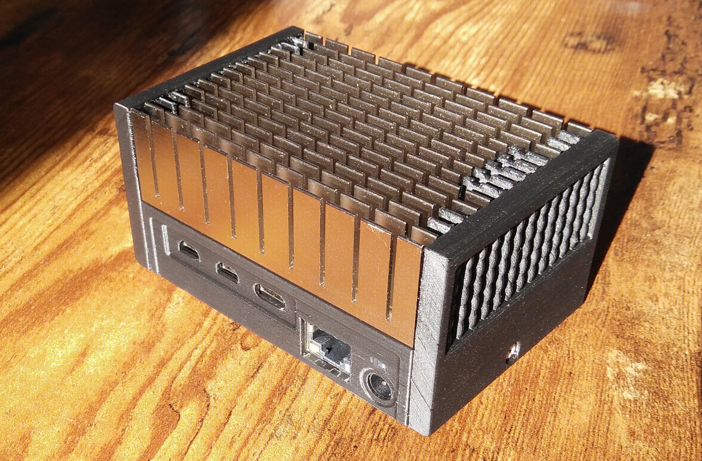
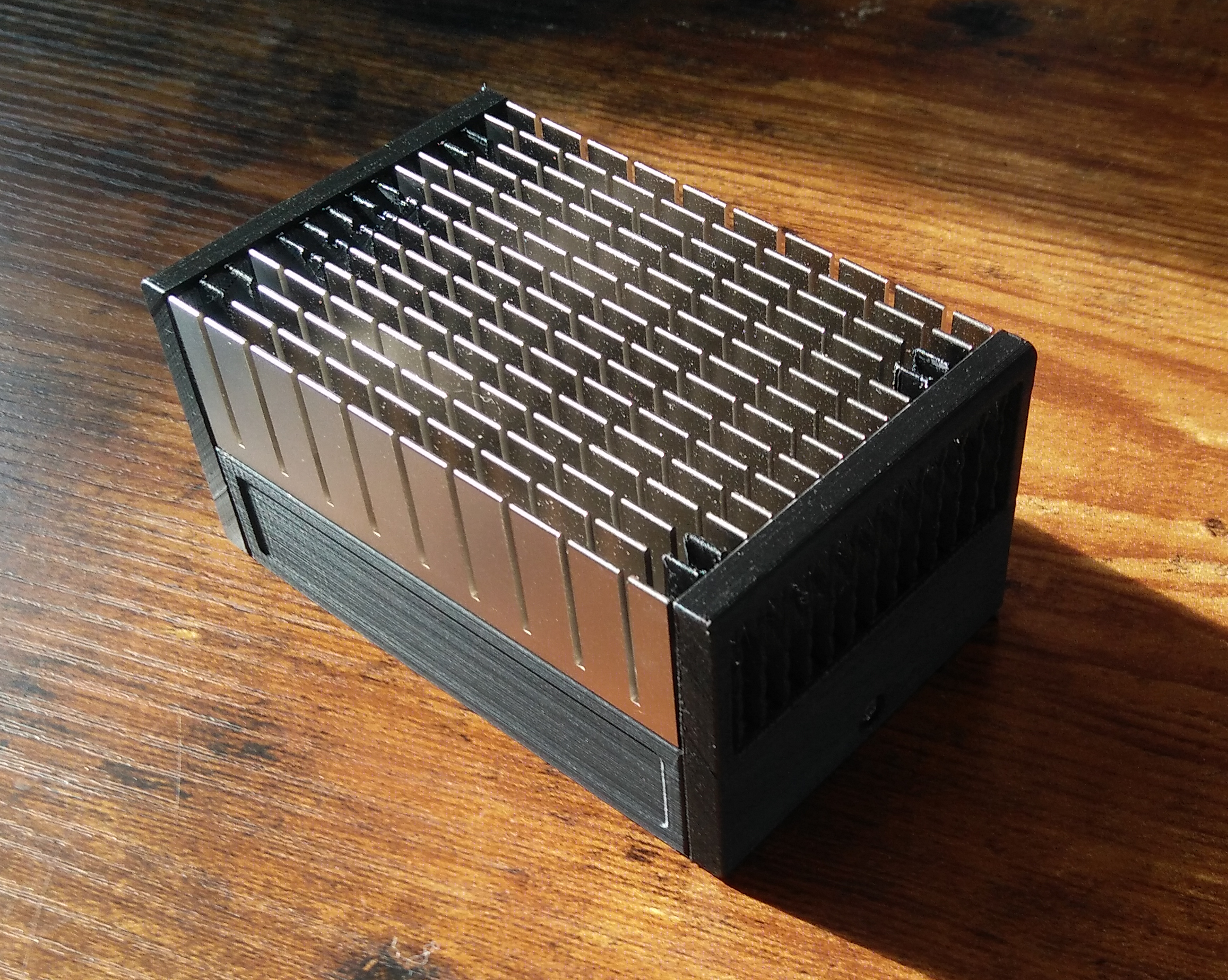
The case was designed to be printed with an FFF/FDM printer with a 0.4mm-Ø nozzle.
The GHF51 heatsink can reach 70-80°C, which is beyond the thermal resistance of typical FFF 3D-printing plastics like PLA. I printed the case with _Extrudr Greentec Pro_ filament, which according to the manufacturer has a higher heat resistance. If it doesn't hold up to the temperatures, I'll write an update here.
Slicing
I used Cura.
Main piece (Case-1)
Print with support for the power socket and ethernet openings.
HDMI, USB, and lightguide openings and the holes for the threaded inserts don't need support; use the support blocking feature for that (Cura).
Side pieces (Case-2 and Case-3)
Printing the two side pieces at a 45°-angle on an edge results in a nicer surface finish and easier support removal. The fins end up a bit more fragile this way, compared to printing flat/face-up.
I had good results with tree-supports and brim.
Make sure to set the seam orientation to the back of the part. Otherwise the fins won't turn out as nicely.
I printed at 220°C/60°C nozzle/bed temperature.
Unless you've got an amazing(ly well configured) printer, expect to do some part cleanup, due to stringing/oozing and the somewhat intricate geometry.
Components
You'll need the following additional components:
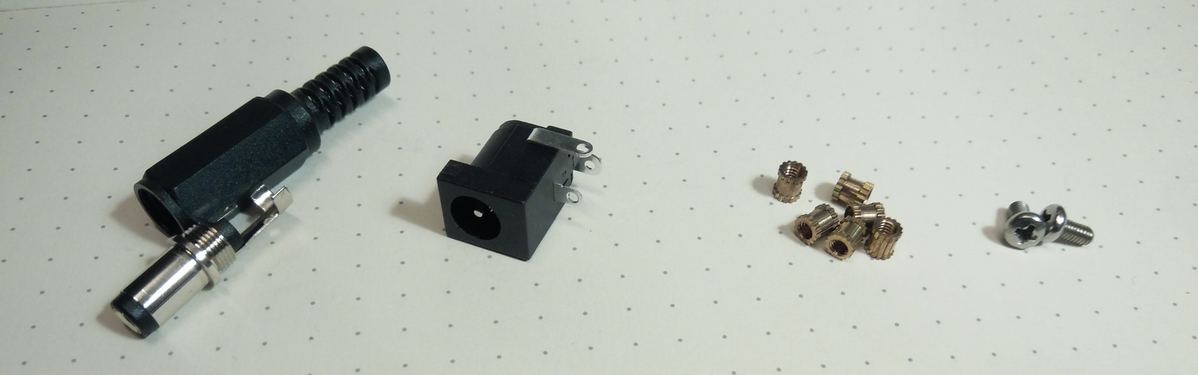
Barrel connector plug: Any outer-Ø 5.5mm, inner-Ø 2.1/2.5mm, length 9.5mm barrel plug should work. I used a BKL 072111
Barrel connector socket: CLIFF FCR681465. There are other brands with the same dimensions that should work
6x M2.5x4x3.6mm threaded inserts. If your inserts have different dimensions you might have to adapt the model dimensions accordingly.
2x M2.5x5mm pan head screws
some wire, solder, glue
Assembly
use a soldering iron to insert the 6x threaded inserts into Case-1
squeeze some (semi)transparent glue (e.g. hot glue) into the channel above the power socket to form a light guide
solder barrel plug to power supply
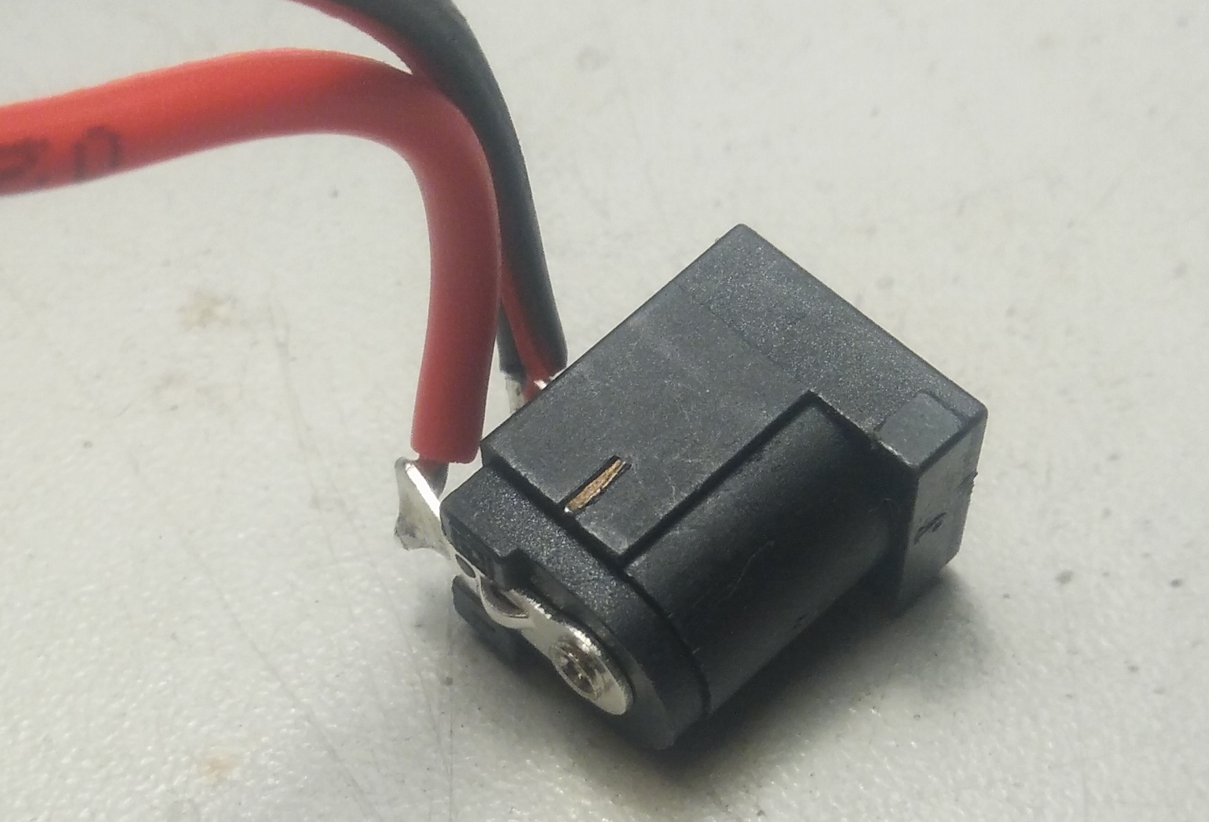
break off the pin on the side of the socket to make it fit into the printed part
solder ~35mm long pieces of wire to the socket pins
push socket into the corresponding recess
connect socket/wires to the screw terminal block on the board
screw board+heatsink to the case with the included 4x M2.5x14mm screws
screw side pieces (Case-2 and Case-3) to the case with 2x M2.5x5mm screws


 0
0 0
0 0
0