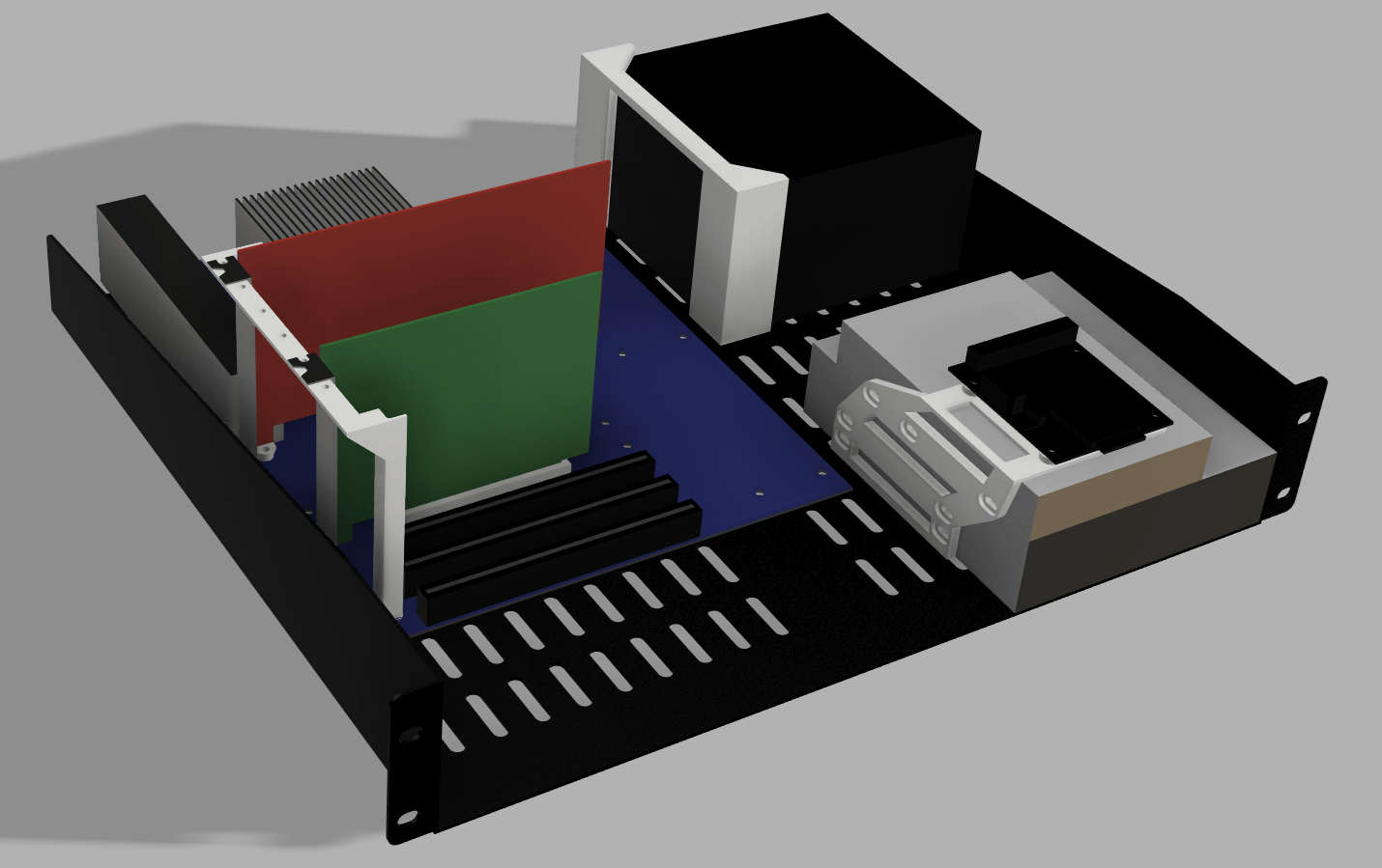
A couple years ago I wanted to start having LAN parties with my retro PCs, and as I had recently built my home network, I came up with an idea for a self-contained LAN party using a network rack. I wanted to put 4-5 full retro PCs into a rack, each mounted on a shelf. Finally, after a year or so of tinkering with the project on and off, I have a functional solution.
Objective:
Mount an entire, fully functional retro PC, including accessories, to a rackmount shelf as simply and easily as possible.
Requirements:
Fit within 3U height ✓
Accommodate both ATX and uATX motherboards ✓ (even mini-ATX included!)
Accommodate full sized ATX PSU ✓
Include mounts for 5.25" drive, 3.25" drive, and SD-IDE adapter ✓
Properly locate/brace/hold down expansion cards (minimum of one AGP video card and one PCI sound card) ✓
All typical ports/connectors accessible X (some workarounds included)
Have easily accessible hardware power and reset buttons ✓
Simple bolt-in solution with minimal to no modification of the shelf ✓
Require minimal hardware and no special tools or other equipment ✓
No funny business--no awkward installation steps or having to force things to fit ✓
Additional Goals:
Accommodate a 120mm fan for some airflow ✓
Option for ITX and AT motherboards (maybe later)
Option for 3.5" and 2.5" drives for modern storage solutions (maybe later)
Semi-professional look (let me know what you think!)
The Solution:
I used the ATX and PCI specs to create an accurate model of a motherboard and expansion cards. I used this to create a set of easily 3D printable mounts. These bolt to a readily available 19" rack shelf from Startech, which I also modeled accurately using the technical drawing that they conveniently provide on their website. The mounts are attached using M3 screws and 3D printed brackets. The brackets locate the mounts accurately using the air vent gaps on the floor of the shelf. Additionally there is a bracket which holds down the PCI expansion cards as well as prevents them from wobbling side to side. All parts print in standard PLA. Most are thin/small enough that there isn't much infill required, but where relevant, I recommend at least 20% infill unless you have quite a few walls. The motherboard adapter is split into two pieces to fit most print beds.
The Not-So-Great:
Now…there are unfortunately a couple of compromises I had to make…
The biggest downside of this design is that there is little space between the “external” I/O area and the side of the shelf. Meaning it is difficult and in many cases impossible to plug connectors in to the I/O ports. For USB mouse and keyboard, wireless dongles are very small and will plug in easily. For ethernet, there are 90 degree cable adapters that avoid tight bends on a standard cable. The video and sound card ports sit high enough that you can plug in cables without any issue, provided your particular cards have the necessary ports toward the top, or you can use a 90º adapter. For LAN parties, this is really all you need. Any additional USB connections can be brought out to PCI brackets using the USB headers on the motherboard. Look for brackets that have ports toward the top for the best clearance. If you MUST use a PS/2 keyboard or mouse, I have a 90º adapter PCB that I designed, but it is not officially released at the moment…
The air vent slots on the floor of the shelf are not perfectly aligned with the spacing for PCI cards. If your motherboard uses the first position for its video card slot (AGP or PCIe 16x slot), the I/O bracket for the card will collide with the shelf. You will need to cut away the section between two of the vents to allow fitment. This is the ONLY modification you may have to do to the shelf for typical fitment. The only other possibility is that, depending on the amount and location of additional slots available on your motherboard and the number of additional cards you intend to use, you may have to cut away more of these sections. If your motherboard uses the second position for the video card (quite common!) and you only need to use one or maybe two additional cards, you will likely not need to do ANY modifications.
Position 1 is roughtly in-line with the mounting hole directly next to the I/O area on the motherboard
Note where the bracket (green) collides (red X) with the section between air vents (circled in red on the next slot over)
HOW TO ASSEMBLE:
Non-printed Parts Needed:
Startech 2U 16" deep 19" rack shelf (CABSHELFV)
Assortment of M3 screws, 6mm to 10mm in length, plus associated screwdriver
That's it! Aside from PC parts as necessary for your build of course
Note--any expansion cards must not be greater than ~110mm from the bottom of the connector to the top of the PCB or cooler. Low profile cards may be best for modern builds, but you will need a 90 degree HDMI/DP/etc. cable.
Second Note--PSU must be standard 140mm length. Check your PSU as some are longer or shorter. I suppose shorter will fit but it won't be secure.
Printed Parts Needed:
1x Lower Motherboard Adapter
1x Upper Motherboard Adapter
1x PCI Card Bracket
1x PSU Bracket
1x Drive Bracket
5x Motherboard Vent Slot Keys
4x PSU Adapter Vent Slot Keys
2x Drive Adapter Vent Slot Keys
1x uATX Spacer (If using a microATX motherboard*)
Additional Parts Recommended:
90 Degree ethernet cable adapter (I used this one from CableCreations -not affiliated- https://a.co/d/9MAfQ6x)
USB PCI Bracket (This one from Startech has the ports located high up which is nice -still not affiliated- https://a.co/d/aXV4Na2)
Assembly Steps:
Start by printing all of your required parts. The are pretty straightforward to print and require minimal supports if oriented correctly. I do recommend supports for the following locations.
Recessed screw mounting faces on the Drive Bracket and Slot Keys
Long bridges on the Drive Bracket where the SD-IDE mounts (print this with the left side face down)
Lower screw mounting faces on the PCI Card Bracket (print this with the top face down)
I have supplied gcode for each of the pieces in case it helps anyone. These printed great using a Prusa Mk3s+ with Atomic PLA (not affiliated but I highly recommend their filament!).
Once you have your parts printed, mock up the Motherboard Adapter and motherboard to confirm whether you need to cut any of the vent slots. The top edge of the motherboard should be in line with the rear edge of the shelf. If you need to do any cutting, I recommend a dremel type tool or similar for precision. Do any cutting of the shelf PRIOR to mounting anything to avoid getting any metal on any of your delicate electronics!
Next I recommend pre-threading all of your screw holes. I chose to have the screws go directly into the plastic to avoid nuts which could cause a short circuit on the motherboard. They should be rather tight (though tolerances will vary depending on your printer) so it will be difficult to get things lined up and threaded when in place if you don't pre-thread the holes.
Pro-tip: when threading a screw into a plastic with an EXISTING thread, start by turning counter-clockwise while applying a small amount of pressure. Once you feel a “click”, then start threading clockwise. This ensures that you are threading the screw into the existing thread and not creating a new thread or cross-threading.
Once everything is threaded, I recommend installing everything in this order (starting with the shelf flipped upside down):
NOTE: THE SCREW LENGTHS ARE IMPORTANT!!! For through holes, if you come out the other end, you may create a short circuit on the motherboard or run into the shelf on the other side. For blind holes, they are only so deep and you can strip the threads trying to go any further.
Motherboard Adapter - Upper and Lower (6mm screws)
The Motherboard Adapter Keys are labeled M and the arrows should face the front of the shelf
Drive Bracket (6mm screws)
The Drive Bracket Keys are labeled D and the arrows should face the front of the shelf
PSU Bracket w/ PSU (10mm screws)
The PSU can be oriented a couple different ways depending on where the power plug is located and how you prefer to manage your cables. For mine, I settled on facing the fan upward and the power plug toward the front of the shelf. For a low power setup, you may be fine with the fan faced downward.
The PSU Keys are labeled P and have arrow facing both the front and rear, as two will face each direction. The holes should be toward the outside of the PSU.
Note the locations of the Brackets and Slot Keys:
At this point you can flip the shelf back over.
5.25" drive, THEN 3.5" drive, THEN SD-IDE. (6mm screws should be fine for all; no longer than 6mm for the SD-IDE)
You may need to install some of the power and data cables for the drives during assembly if the clearances are tight, depending on the length of the 5.25" drive and the location of the motherboard headers.
Motherboard w/ CPU and cooler pre-installed (6mm screws, but SKIP the holes that the PCI Card Bracket will share*)
PCI Card Bracket (8 or 10mm screws, using the hole to the left of expansion slot Position 1--see above--and the bottom left hole of the motherboard*)
Expansion cards (anywhere from 3-8mm screws, this one is less critical but be careful not to block your ports)
Lastly, install any remaining cables and/or accessories.
*For uATX motherboards, the board will not extend to the lower mounting hole that the PCI Card Bracket uses. In this case, use the uATX spacer to account for the missing thickness of the motherboard.
At this point, everything should be installed and ready to go! I do recommend mounting a fan to the front for additional airflow and easy access to mounted power/reset buttons. See my other model here. Other than that, just install the shelf in your rack and hook up your accessories and go!
Feedback is welcome!
This has been my biggest 3D design project so far, so I am open to feedback! I know there are things that are not completely perfect, and there are probably things that could be changed/fixed. If you use this design, please let me know your thoughts :)
Future plans:
I may adapt this for ITX boards and/or modern 3.5/2.5" drives. If you want this, feel free to reach out.


 0
0 0
0 0
0