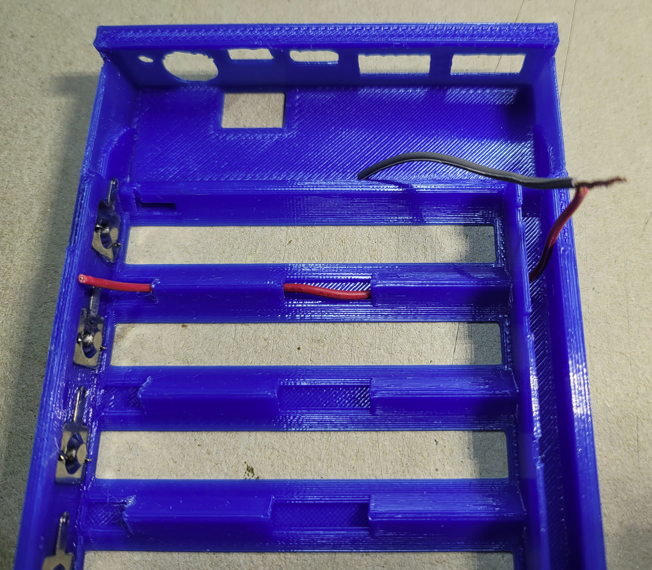
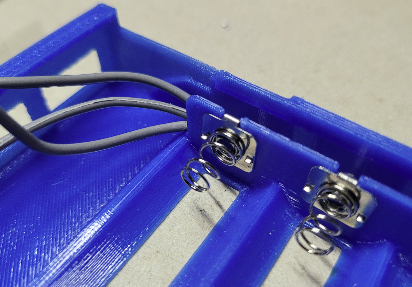
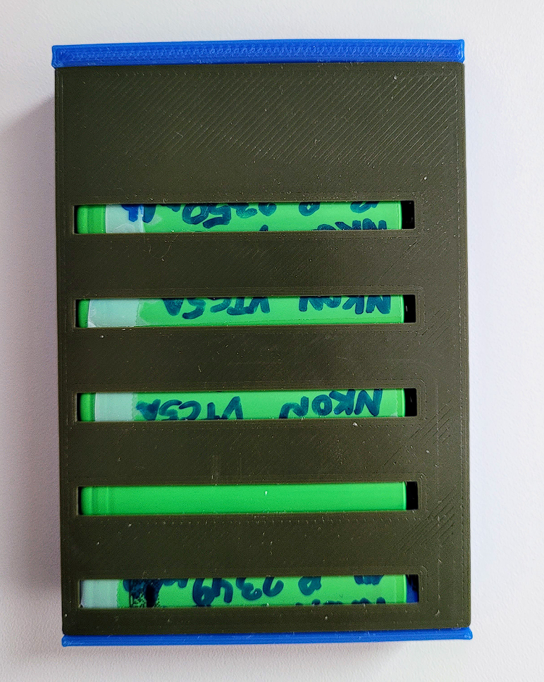
This is my attempt at creating the smallest footprint 18650 battery cell-based battery pack. 18650 Li-ion cells have a lifespan of approximately 300–500 cycles. Therefore, it is very important to me that they can be replaced easily, quickly, and without the need for tools like a soldering iron.
The foundation for this project is a power bank module I found on Aliexpress, which is available in 3S (65W max), 4S (100W max), or 5S (100W max) variants. Different 3D-printed versions for all three variants are available in the files tab.
This battery bank design is also featured as a component in another one of my projects: Ultimate Modular Speaker.
Disclaimer: I am not an electrical engineer. Use and perform this project at your own risk!
Features and Design Considerations:
Small footprint: Approximately half the size of a standard power tool battery.
Easily replaceable battery cells: No tools, like a soldering iron, required.
Charge balancer: Ensures proper charging of all cells.
High-power capabilities: Supports 100W (20V 5A) charging and discharging via USB-C, suitable for both smartphones and laptops.
Extra connectivity options:
Outputs: 2x USB-A
Inputs: Lightning, Micro USB, DC-Port
Battery percentage indicator: Displays the charge level.
Overheating protection: Includes a temperature probe for added safety.
⭐Parts:
3D Printed: (PETG/PLA etc.)
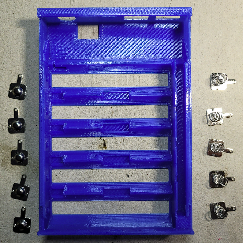
Case (3S, 4S, or 5S versions)
Cable cover (3S, 4S, or 5S versions)
Cover (3S, 4S, or 5S versions)
Note: Support material is required for certain areas during 3D printing.
3-5x 18650 battery Li-ion cells ideally with a high C rate (due to overheating issues)
Soldering iron plus solder
⭐Assembly:
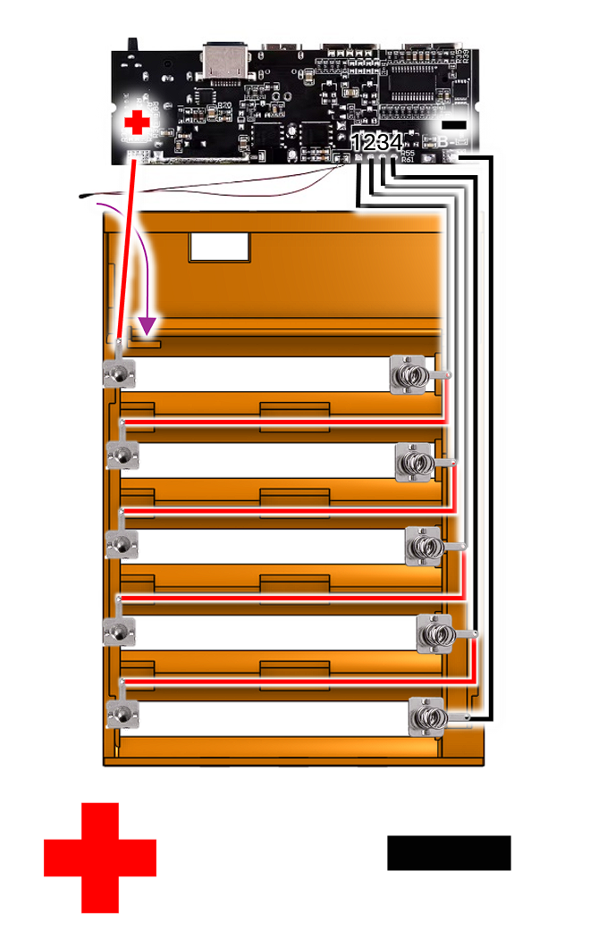
Wiring diagram
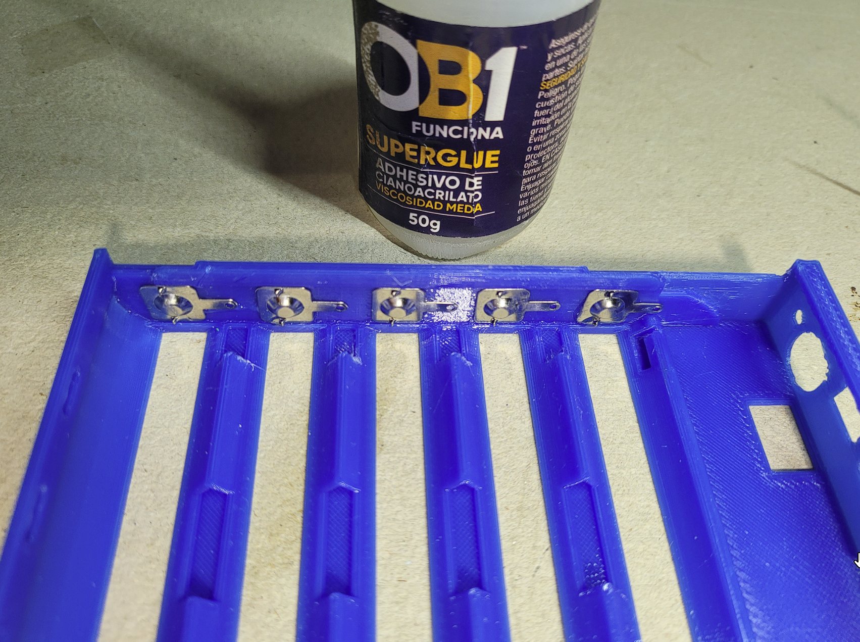
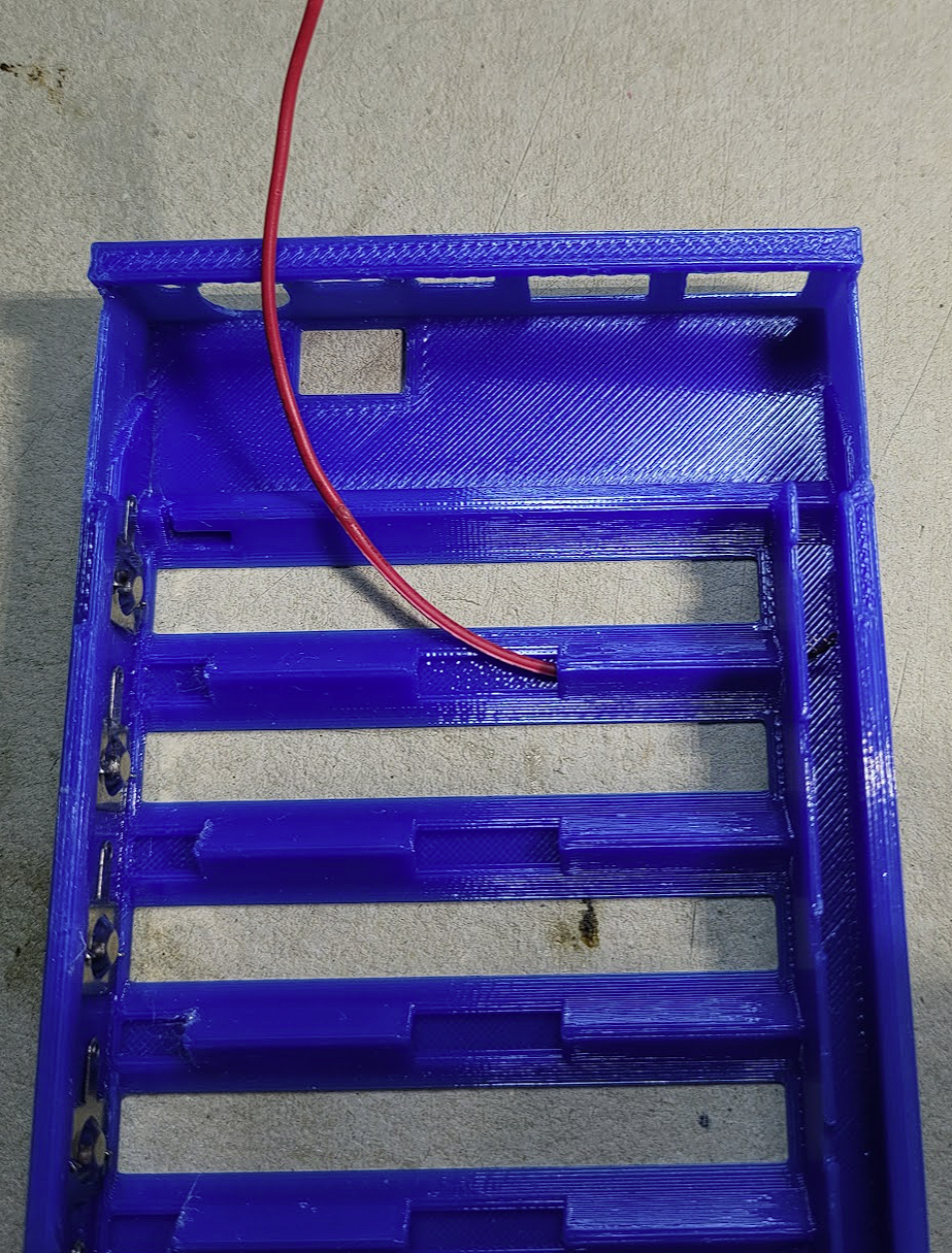
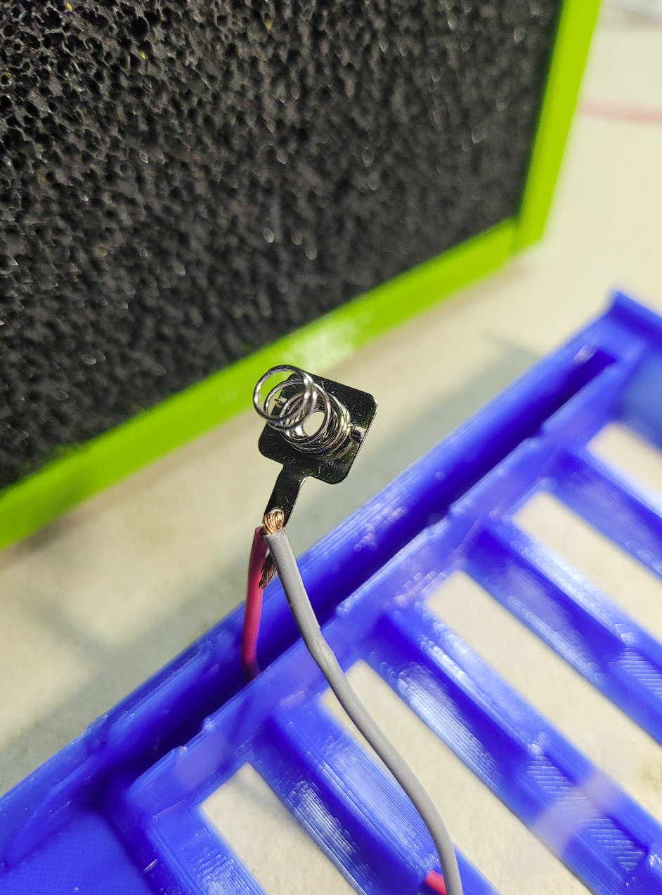
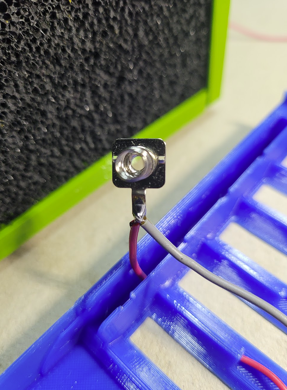
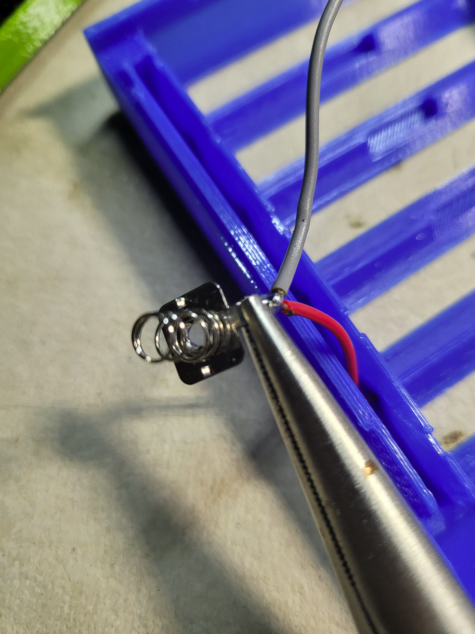
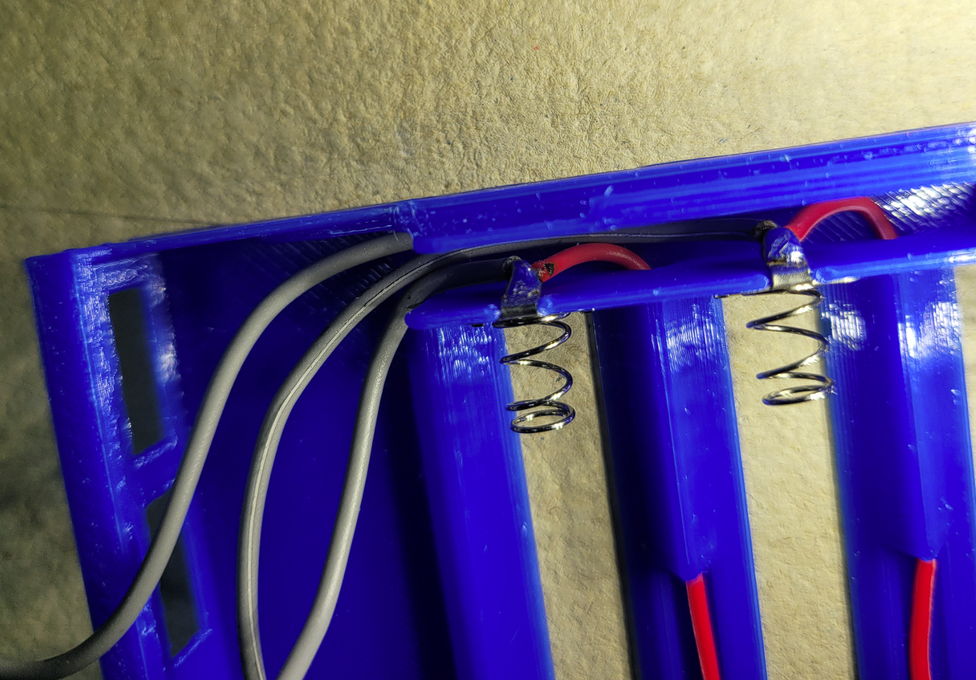
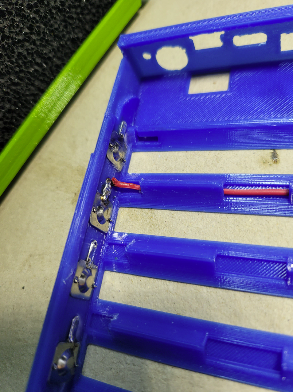
Soldering Step by Step:
Tips:
Battery alignment: All positive battery terminals should be on the left side, and all negative terminals on the right.
Temperature probe: Secure the temperature probe in place using tape or another adhesive.
Cable cover installation: Insert the cable cover last. It is designed to hold the cables in place when replacing the 18650 cells.
Balancer cable connection: Connect the balancer cables in order: 4-3-2-1, followed by the minus cable, then the plus cable. This order isn't critical if no batteries are inserted.
PCB placement: When inserting the PCB into its designated slot, ensure the button doesn’t get stuck.
Cover fitting: Squeeze the case part slightly to ensure the cover fits snugly.
Initialization: After everything is connected, the battery cells are inserted, and the lid is closed, the battery pack must be connected to a charger to initialize the board. This step is required every time the 18650 cells are replaced!
⭐Performance testing:
Overall, I believe I achieved my goal! This battery pack powers my old HP laptop with an i5-7200U for approximately 2.5 hours using four 3000 mAh cells, which is great.
Discharging: No overheating observed during discharging.
65W charging: Rare overheating with a 65W charger.
100W charging: Fast overheating occurs when charging at 100W.
All files are free to use and available as STEP files. Feel free to remix them to suit your needs! 🙂


 0
0 0
0 0
0