
Conjugate cam - educational model
Sophia Hopkins

Encuentre similares con IA


Perfil de impresión(0)
Archivo de modelo(0)
 0
0 0
0 0
0
Publicado:2026-05-04 08:27:15
0
0
 000
000This model is one of my educational mechanical mechanism examples, based on an 80 mm x 80 mm base plate.
You can find all the models of this series in this collection =>[Examples of Mechanical Mechanisms]

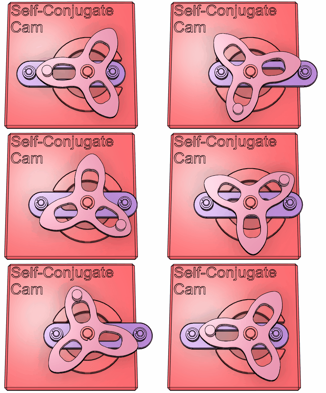
These are educational models of conjugate cams. One of them is a regular conjugate cam, and the other is a self-conjugate cam.
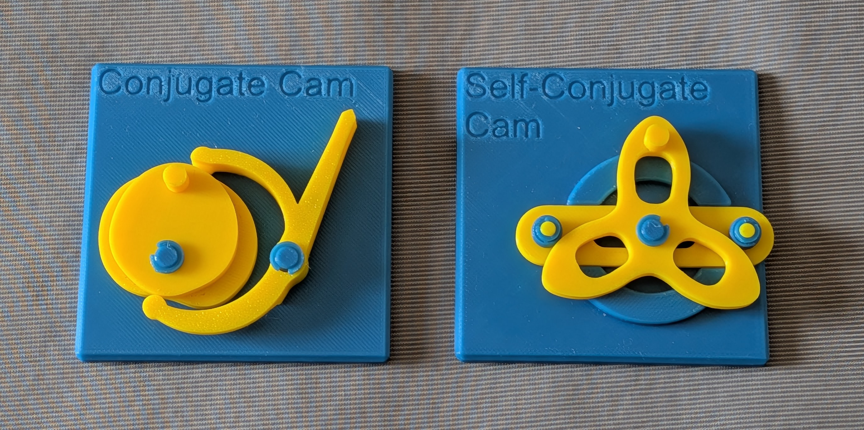

In a typical cam mechanism, the driven member is only constrained by the cam in one direction. Therefore, gravity or a preload provided by a spring applied from the opposite direction are needed to keep the driven member in continuous contact with the cam; otherwise, the driven member will separate from the cam profile, and the intended motion will be interrupted. Even with a preload, at high enough speeds, the driven member may still lose contact with the cam profile. To extend this one-way constraint to a two-way constraint, the preload can be increased.The second cam, constraining the driven member from the opposite direction. The two cams are designed in coordination, so that they apply the same motion law to a pair of driven members rigidly connected together from two directions, thereby completely constraining the motion of the two driven members with fixed relative positions.And it doesn't rely on springs or gravity.The added cam is conjugate with the original cam, and this overall arrangement is calledConjugate cam mechanismOr, when emphasizing positive motivation, it is calledForced cam mechanismThe word 'Desmodromic' originates from the Greek words 'δεσμός' (desmós, meaning 'bond') and 'δρόμος' (drómos, meaning 'path'). This term is most commonly used in the context ofValve drive of a four-stroke engineIn this context, the conjugate cam opens and closes the intake and exhaust valves without the need for valve springs - this arrangement is known asForced valve drive。
In the first mechanism shown here, the top cam was originally designed to be mirror-symmetric, and the bottom cam was designed to be the conjugate of the top cam. Please note that the bottom cam is not mirror-symmetric, because the movement of the driven member relative to the mirror is asymmetric.
In the second mechanism shown here, the width of the cam curve remains constant when measured along any straight line passing through the cam pivot, which allows a single cam to simultaneously act as its own conjugate. That is, a cam alone simultaneously constrains two opposing driven members, eliminating the need for independent conjugate cams. In this sense, we refer to this cam mechanism as a self-conjugate cam, although this term is not commonly used. Since only one cam is required, the number of parts and assembly tolerance requirements are reduced; on the other hand, the inevitable trade-off is that
This model is compatible with meThe first compilationThe shell in it.
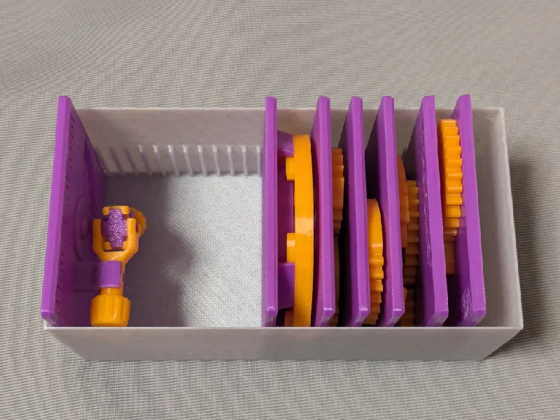
Please note that in this model, the rotation of the bearing base is intentionally not made too smooth.
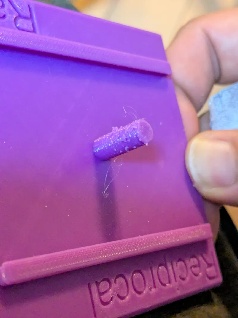
Sometimes, the gears may exhibit a drawing effect and/or a claw effect, resulting in an overly tight fit with the shaft
If you see a rough surface on the shaft due to drawing, please use a small piece of sandpaper to polish off the rough parts.
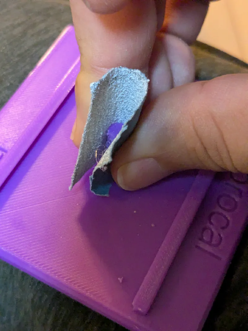

If you think that the gear can't rotate smoothly due to the elephant foot effect, please use a fine round file to slightly enlarge the hole.

If there are no such problems, the parts should rotate very smoothly with minimal friction.
Fix the parts with clamp rings.
You might also be interested in the models in my examples of educational mechanical mechanisms.
You can find them in this collection:
https://makerworld.com/collections/15048577-my-educational-mechanism-models
Have a nice printing experience!
The reason why I became interested in gears is thanks toK. SuzukiIt's wonderfulArticleAndYouTube videoMany of the institutions showcased in this series originated fromHis websiteThe introduction on the website. He also made it himself.An excellent gear model. Without his inspiration, this series would not exist.
I'm fromHaguruma-No-Hanashi WebsiteI've learned a lot of technical details about designing gear profiles. I'm very grateful for that.
