
Simple LM2596 Case (Single Piece)
SaltyArch07

Find Similar with AI


Print Profile(0)
Model File(0)
 0
0 0
0 0
0
Published:2025-12-21 15:03:54
0
0



 000
000This is a simple single piece case for an LM2596 DC - DC buck converter. There are several versions of this module but this case is specifically for the version pictured below. It has two mounting holes, a voltage adjustment potentiometer, no screw terminals, and no screen.

This is a very basic case that covers all the conductive bits of the module while keeping access to the voltage adjustment screw.
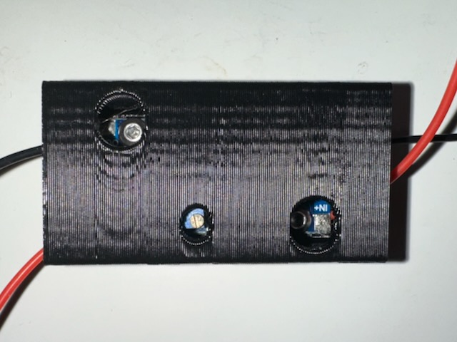
The M3 bolts should be 8mm long and the self tappers a maximum of 5/16" long so the fasteners don't poke out the back of the case.
I designed the model to be printed in the default orientation with supports. The mounting posts on the inside of the case have flats modeled into the bottom for the support contact point. I prefer Orcaslicer so I used organic tree supports but anything else will work fine.

I printed mine in PETG with a 0.4mm nozzle at 0.3mm layer height with 2 walls. Infill doesn't matter since the print is mostly walls. Any other material will work fine.
I have two versions of this model. One version uses two 8mm M3 bolts and M3 nuts. The nuts press into the case snugly and once assembled, both the 8mm bolt thread and nut sit flush against the back of the case.
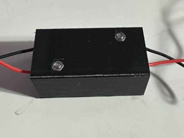
The second version is identical except instead of using an M3 nut and bolt, it uses two #2 self tapping screws that thread directly into the plastic.
An important note about the way I set the hole dimensions:
My Ender 3 KE prints small holes about 0.015" undersized. I modeled the M3 bolt clearance hole to be 0.127" (3.25mm) and the nut hex dimension to be 0.225" (5.72mm) flat to flat. On my machine this results in a snug fit.
The #2 screw hole diameter is modeled as 0.078" (1.98mm). The actual nominal minor diameter for a #2 screw is 0.064"-0.067" so this ends up with solid thread engagement for me.
If you have any issues with fitment with the clearances I modeled, let me know if it ends up too loose or tight for your machine and I can maybe release some different versions with a range of clearances.
