Handwire Hotswap-Socket
module_beam

Mit KI Ähnliches finden


Druckprofil(0)
Modelldatei(0)
 0
0 0
0 0
0
Veröffentlicht:2026-06-06 12:48:23
0
0
 000
000This is a hotswap socket for MX style switches allowing you to not permanently solder in switches for handwired mechanical keyboard builds. The socket goes well with the handwire guard (shown in the middle):

If you use 1.0mm diameter wire (approx. AWG18), the switch can be pulled out of the socket. For insertion, it's better to support the socket from the back.
While it is possible (and I have done so) to use this model with PLA and ABS, I would recommend to print the socket using TPU filament as it is a bit more flexible and forgiving in terms of printer and switch tolerances.
Layer height: 0.2mm
Infill: 20%
To assemble the socket you'll need a diode (e.g. 1N4148). Before assembling the socket you should decide on the direction for the diodes. Whether all diodes have the same direction or not is up to the matrix you choose for building your keyboard.
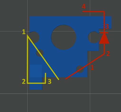
All of the following directions (i.e. left, right, top down) are given relative to the image below.
Preparation:
Cut the diode wire approximately 2/3 on one side of the diode
You now have an off-cut wire (yellow) and a diode with wires on both ends (red)
Yellow wire:
Push the off-cut wire into the socket from the left side
Bend the wire down and put it through the hole
Bend excess wire upwards
Red wire:
Put the diode (red, ensure correct cathode/anode orientation) into the socket from the right side
Make bend before the diode
Put wire after diode through hole at top right. Use pliers to pull the wire through the hole (apply gentle force if needed)
Bend wire to the left or coil wire as desired
Make sure that yellow and red wire are not connected at the bottom.
After assembly, the socket needs to be 'broken in'. To do this insert a switch in to the socket. During the first insert, the wires will be bent by the switch contacts. This means that a considerable amount of force is required. Due to this force the switch pins can deform. Therefore its best to use a spare "sacrificial switch" for breaking in.
If the switch does not make contact after soldering, you may have applied too much heat and the material has deformed. Use a multimeter to find out which switch pin is not making contact. Usually the problem can be fixed by inserting another wire into the socket to make up for the deformation.
The original model is published under the "Unlicense". As I intend to share the model with the same license as the original work, I selected the CC - Public Domain license as it seemed the best fit for the original license.