
PCIe Rack Mount (10" 1U)
Douglas Fuentes

Mit KI Ähnliches finden
Druckprofil(0)
Modelldatei(0)
 0
0 0
0 0
0
Veröffentlicht:2026-04-15 11:45:59
0
0



 000
000Modification is required for the “Caddy BASE” model.
Provides full-height (standard) PCI slots, not low-profile slots.
1U will fit a 2 slot card. But if you have clearance below, you can mount a 2.5 slot card. I have not tested 3+ slot cards.
This is a 3 piece print. The front and back are universal, but the “caddy” will need to be modified, because there's no standard mounting for PCIe risers, etc.
I used PETG, but should work with any rigid material that can handle the heat of your PCIe card. (That means use PLA with caution.)

Print with the front on the print bed.
Enable supports for the large bridge between the slots.
Using either 0.2mm or 0.1mm layer height for the optional distance markers on the side to print properly.

Same orientation. No supports required. Any layer height.
Take the Caddy BASE.step file and modify with the following:
1. Add screw holes for your specific riser/adapter and mounting solution (inserts or threading into plastic).
2. If necessary, add cutouts for components on the back of the PCB that prevent a flush mount.
3. If necessary, extend the width of the caddy to support very deep racks.

(The example modifications I made for my specific PCIe to M.2 adapter.)
Measuring tips
You can print the unmodified caddy, assemble and use a marker to mark the mounting holes.
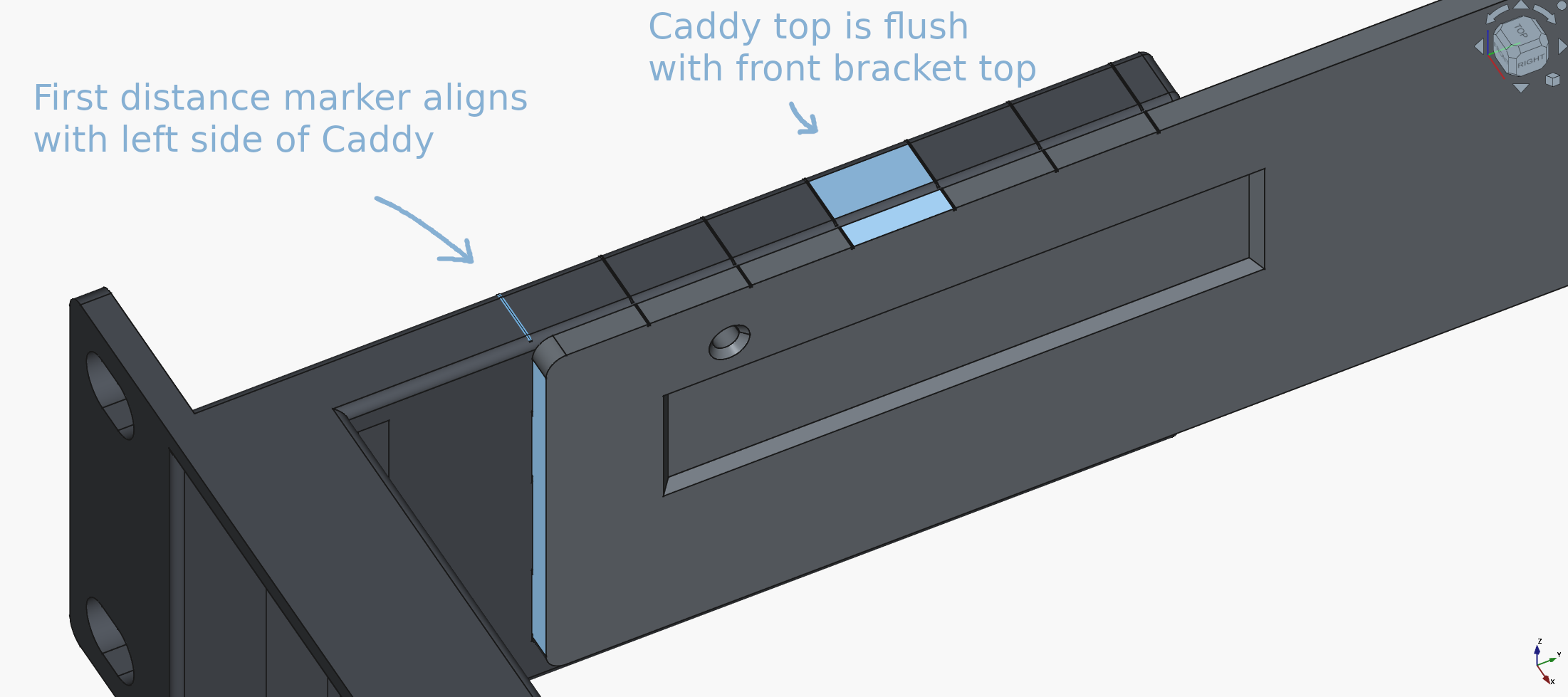
Or you can assemble without a caddy and use the measuring guides on the front bracket.
Either way, plug your PCIe card into the riser/adapter slot and then assemble as below.

Orientation as per screenshot. No supports. Any layer height.
1. Insert the caddy into the front bracket.
This is supposed to have some friction but not be permanently stuck in there.
If the fit is too tight I recommend using a file to make it easier to insert and remove.
If the fit is loose this isn't a problem and the print should still be functional.
The triangle on the caddy should point up.
2. Test whether the rear bracket slides easily.
The rear bracket MUST easily slide along the caddy.
If this fit is too tight use a file to ensure it can easily move.
Otherwise tune your printer's dimensional accuracy or adjust the model to fix.
Make sure the caddy is inserted all the way into the front bracket.

3. Mount your PCIe riser/adapter.
If you've already modified the caddy model for your riser's mounting holes, attach it to the caddy.
If you're measuring the location of the holes, instead plug the PCIe card into the riser's PCIe slot.


4. Screw your PCIe card into the front.
Insert your PCIe card and use the PCIe slot screws to securely mount it.
Note: this requires threading into plastic!
Make sure the screw is straight, use enough force to thread, but don't strip the hole.
If the hole is stripped, you may have to print another copy of the entire front piece.

(Optional) add a PCI slot cover if you're not using one of the slots.
5. Mount the rear bracket to your rack.
Using standard rack screws / studs, mount the rear bracket to the rear rails of your rack.

6. Mount the assembly to the rack.
Insert the PCIe card + riser + front panel assembly from the front of the rack.
Make sure the caddy slots into the rear bracket.
Using standard rack screws / studs, mount the front to the rails of your rack.


