Accelerometer mount for Sparkfun LIS3DH breakout board
Jennifer Griffin11

Mit KI Ähnliches finden


Druckprofil(0)
Modelldatei(0)
 0
0 0
0 0
0
Veröffentlicht:2026-01-22 11:18:00
0
0



 000
000There's some great documentation on how to use an accelerometer with a Prusa MK4 to measure the parameters needed for tuning input shaping here:
https://github.com/MCDELTAT/MK4_Accelerometer
I'm using a Sparkfun LIS3DH breakout board for this:
https://www.sparkfun.com/products/13963
It works great with the addition of a 2.2k resistor between CS and GND pins, as described here:
https://github.com/MCDELTAT/MK4_Accelerometer/issues/1#issue-2311419897
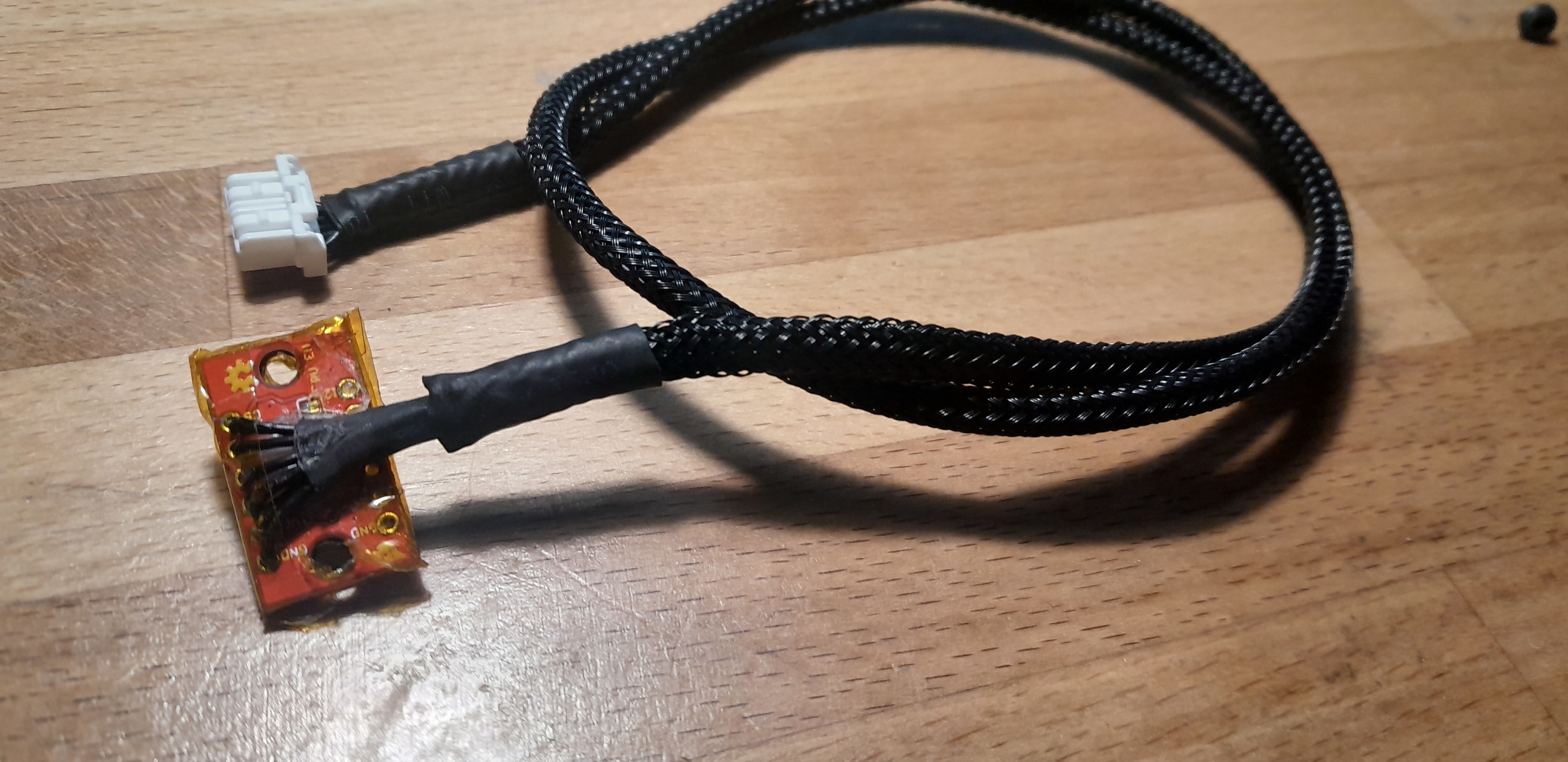
The accelerometer should be mounted as rigidly as possible to give accurate measurements.
That's what these two models are intended to do.
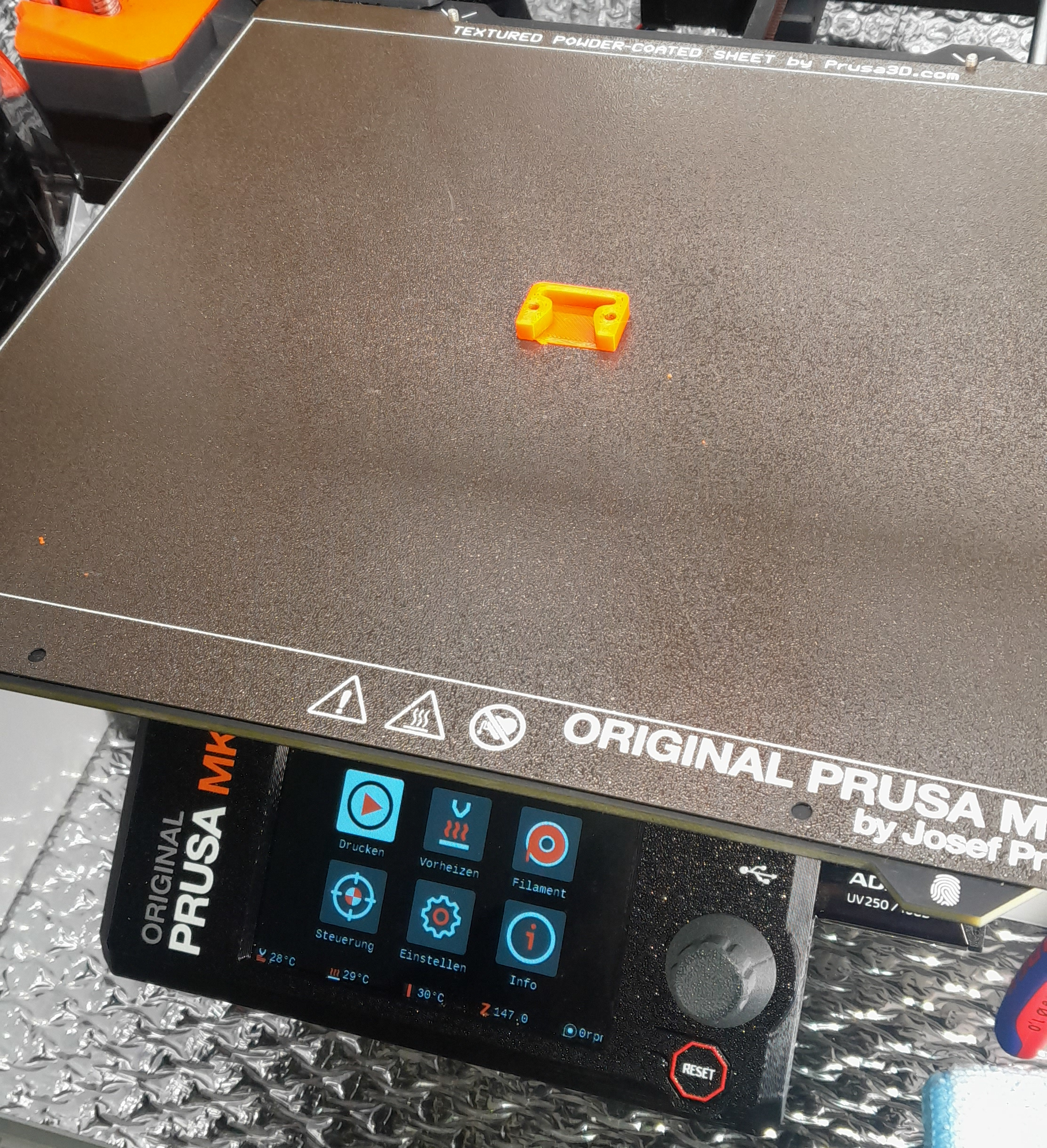
To measure the Y axis, print out LIS3DH_Holder_Bed.
Make sure to disable the “turn off heatbed” line in the End-Gcode in your slicer, so the holder stays attached to the center of the heatbed for the duration of measurements.
This is a one-time use part as it will come loose from the bed once it cools down, but it prints in just 5 minutes and uses just 1 gram of filament.
I found that printing it with 4 perimeters and 0% infill gives good results:
The LIS3DH breakout board can then be mounted with 2 M3x5 screws like this:

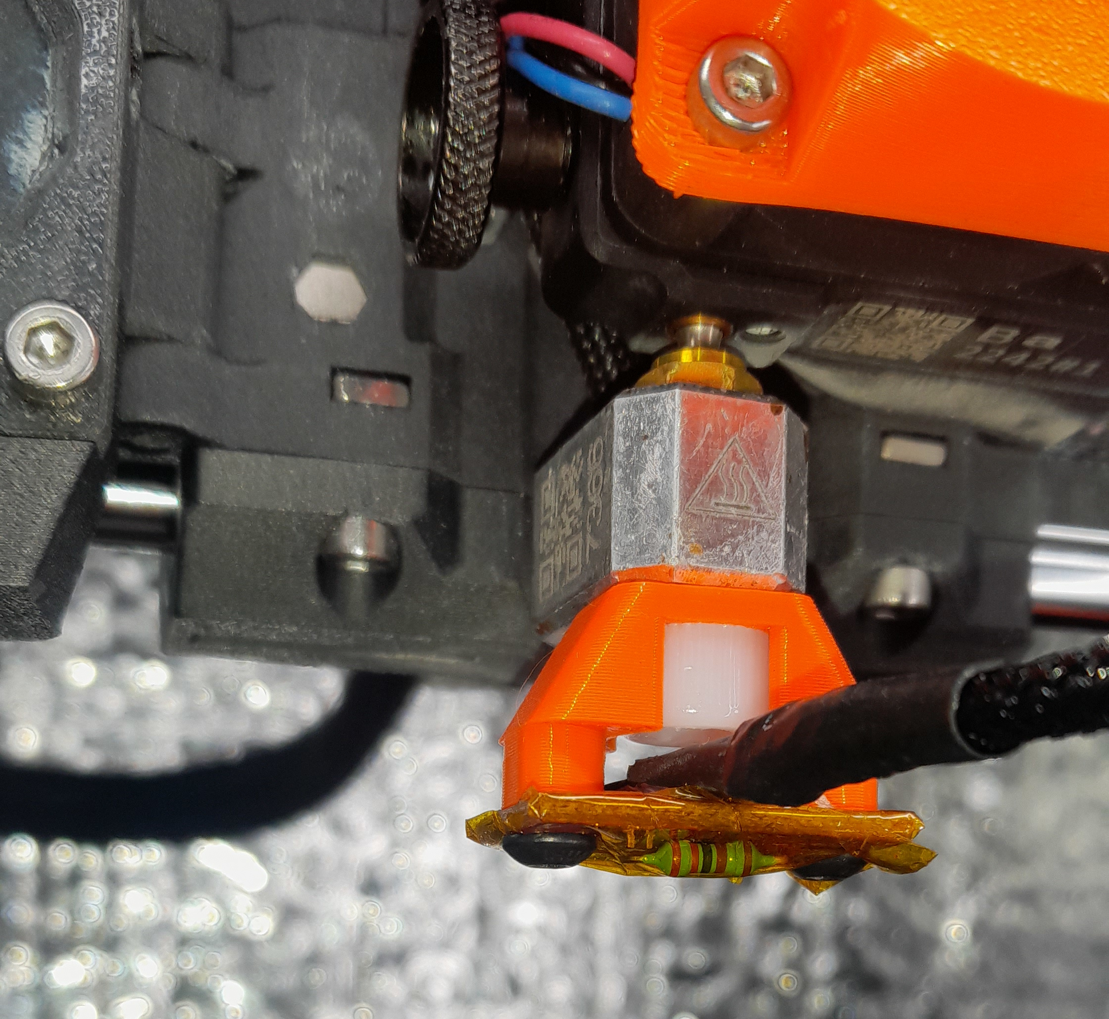
To measure the X axis print out LIS3DH_Holder_Nozzle with 100% infill, as we want the part to be as rigid as possible.
Then unload the filament and let the nozzle cool down completely. Now unscrew the nozzle from the heater block and mount the printed part to the heater block with a M6x8 nylon screw instead:
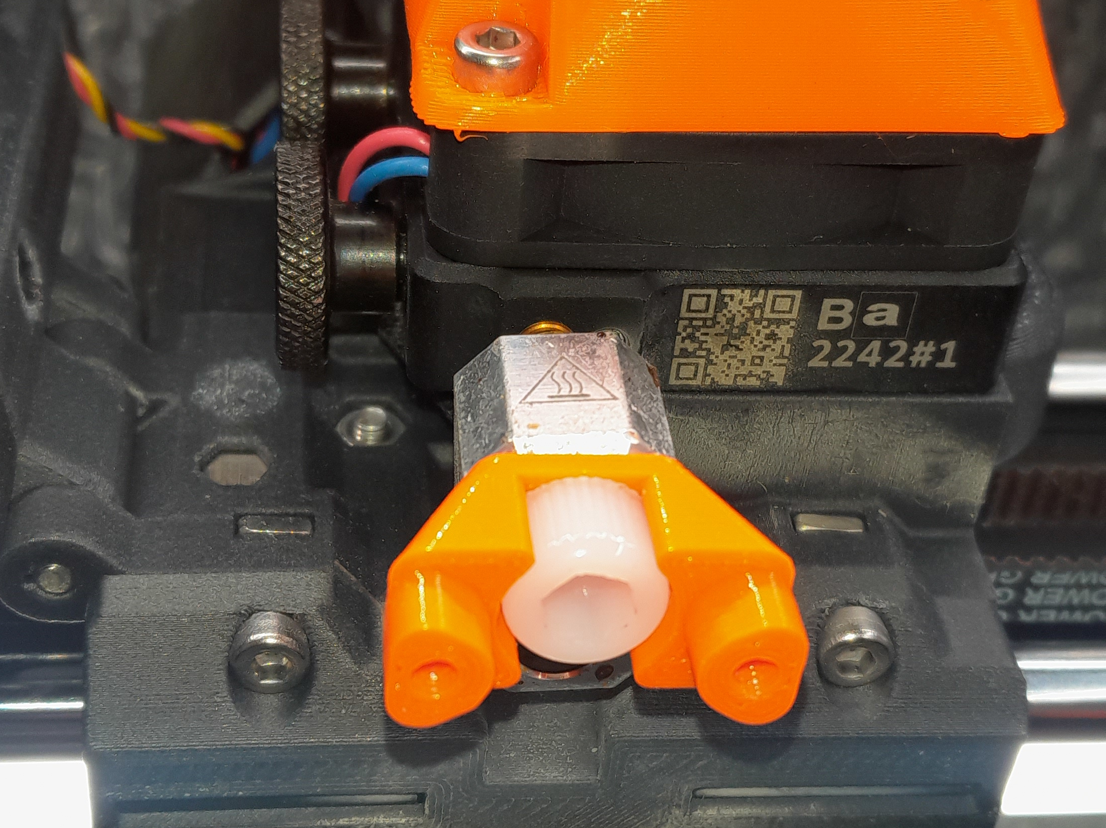
Then you can mount the LIS3DH breakout board with the same 2 M3x5 screws that were used for the Y axis: