AXJ UV camera
digital_studio

Mit KI Ähnliches finden


Druckprofil(0)
Modelldatei(0)
 0
0 0
0 0
0
Veröffentlicht:2022-02-26 19:05:50
0
0
 000
000Ever wonder at the world of insects, birds, reptiles, and fish that see ultraviolet as a separate primary color? This camera lets you take stunning ultraviolet photos in color, by remapping green, blue, and UV to RGB color space.
The magic happens in the filters used, combined with the custom camera software. The Pi NoIR camera, popular for its infrared sensitivity, can also image ultraviolet, though faintly. The specific filters selected for this project compensate for the camera's low sensitivity to UV by diminishing blue and green light, and completely eliminating longer wavelengths that would interfere with taking the photo. These filters are expensive but well worth the price tag for the photos you'll be able to take.
Some soldering required.
Parts List
Please see the Print Settings and Post Printing sections to properly print and set up the camera.
Printer Brand:
Creality
Printer:
Ender 5
Notes:
You can print this in any filament material but IT MUST BE BLACK. (The rear panel doesn't have to be black, but the front panel and top do. Any other parts you can try a different color but it may or may not work.) The reason is the case must block all light, including infrared light, from the raspicam. If your case leaks any infrared, it can ruin your photos. Even a dark blue, green, or brown filament will often look the same as a white/clear filament in infrared. If you're in doubt, you can build an IR camera and photograph your filament under daylight or incandescent light to make sure. https://www.thingiverse.com/thing:4322005 Or you can just build the UV camera and then test it under an incandescent light.
The base can be printed upright without supports; the top can be printed upside down without supports; the power side can be printed standing up without supports. These are the three pieces that have slots for inserting M3 nuts, so you want to make sure they print with functioning nut slots.
The rear panel can be printed on its face without supports. The matte lining works well with matte black PLA, and does not require supports if printed on its narrow end. Print two pineapple rings - matte black is great for these too - one will hold the BG38 filter and one will hold the U330 filter.
The front panel and USB side will require supports. I printed them with the exterior side up and was satisfied with the results. On the front panel, unless you use soluble supports, make sure supports are "on build plate only" since you don't want them in the threads of the objective aperture; they'll be impossible to remove.
Assembly
Use four of the M2 machine screws and nuts to attach the PiTFT display to the rear panel. The 40 pin header of the display will be on the bottom, which you can identify by the angled edge of the printed panel. When facing the screen towards you, the power button will be on your right.
The front panel includes 4 cylindrical supports that have to be broken off before assembly. Then use the remaining four M2 screws and nuts to attach the RasPi NoIR camera to the inner surface of the front panel, ribbon side up. It should now be looking out the viewing hole.
Place the M3 nuts into their slots: 3 are in the base; 4 in the top; 1 in the power side panel. You may have to force them kind of hard. If it helps, you can use a heat gun to soften the plastic (careful not to warp it!) or press the tip of a hot soldering iron to the nut. Conversely, if the slot is too loose, a dab of super glue can secure the nut in place.
Place the 1/4" nut in the hexagonal impression near the center of the base. You may have to force it in.
Place the battery pack inside the large rectangular area of the base. Its charging port should be on the bottom facing out; its USB ports should be above the charging port; its indicator lights should be facing the direction of where the front panel will go; its power button should be on the top.
Place the Raspberry Pi in the support slots right next to the battery, in order to see where it will go. Note the Pi may lean at first; this is normal.
The next step is to wire up the small 2x13 header on the back of the PiTFT. Please refer to this pinout: https://elinux.org/File:Pi-GPIO-header-26-sm.png pin 1 on the device is indicated with an arrow. It's important to connect one of the +5V pins to a red wire that will be soldered to the switch later, and one of the GND pins to a black wire that will be soldered to the USB connector later. The capacitor should be soldered across these two wires, observing the capacitor's polarity.
Solder the black GND wire to the shorter lead of the LED, clipping off the excess portion of the lead. Solder the longer lead to the 470 ohm resistor, and the other lead of the resistor to a green jumper wire and connect that to the TXD0/GPIO 14 pin of the header. It's a good idea to use a strip of paper or some sticky tape between and around the LED wires to insulate them from each other and from surrounding electronics.
Place the switch into its rectangular hole in the rear panel. It should snap into place; if the hole is too tight, remove some excess material with a filament cutter. Solder the red wire to one of the switch's terminals.
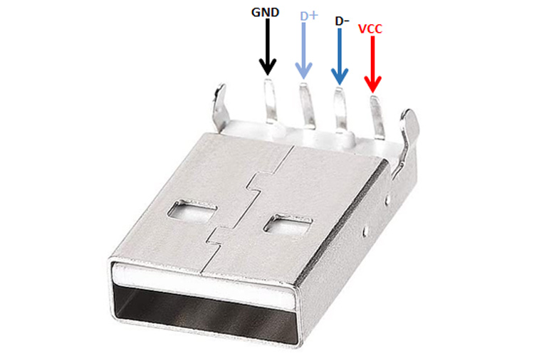
Now it's important to solder the USB connector. Here's a good pinout for reference: https://components101.com/sites/default/files/component_pin/USB-A-Male-Connector.jpg . The GND pin will be connected to your black GND wire, while the Vcc pin will be soldered to a wire that's soldered to the other terminal of your switch. Optionally, a little piece of heatshrink tubing over the USB connector's terminals is a good way to protect the solder joints.
Now it's time to assemble the Pi and the touch screen. Place the 40 pin header on the Pi GPIO and then connect the touch screen to the header. Push them together snugly. Place the Pi back in its support slot; the rear panel should be touching or almost touching the base.
Insert the USB plug into the top port of the battery. Then place the power side panel into position and secure it with an M3x30 screw through the lower right hole of the rear panel, through the hole in the base, and into the nut in the power side panel. Slide the LED into the power indicator window.
Next, place the front panel into position and secure it with an M3x25 screw entering the bottom front corner of the power side panel, through the hole in the front panel, and into the nut in the base. Connect the Raspicam ribbon cable to the camera port of the Pi. The blue side will be facing the Ethernet and USB ports.
Now place the USB side panel into position. Secure it with an M3x20 screw on the bottom rear corner and an M3x30 screw in the bottom front.
Before proceeding to the next step, it's a good idea to test the unit. Connect the HDMI port to a monitor and the USB ports to a keyboard and mouse, and turn the power switch on. Everything should power up; you should see lights on he Pi and the green LED should light; the backlight of the PiTFT will light up, but no picture will appear. This is also a good time to connect the Pi to your Wi-Fi. You may choose to install the software now or wait until later. When you're satisfied all the wiring is good to go, shut the Pi down and turn off the power switch, then disconnect the HDMI port.
Now you're ready to apply the top piece. It will have 4 places to fasten with screws; all of these will be M3x25.
The objective assembly is not difficult but can be tricky. I've had the best luck stacking the filters on top of the (face-down) matte lining, then carefully screwing that into the front panel. Be extra careful of the U330 filter, as it's very thin and therefore very fragile. A good configuration is as follows: matte lining, then 550nm shortpass, then a pineapple ring with the BG38 filter, then the other pineapple ring with the U330. Turn the matte lining until snug, but do not over tighten. The filters will rattle slightly; it's important that they do not fall out of view of the Raspicam.
The last assembly step is to cut a length of cording, about a meter or about a yard should be enough, and tie a knot in one end. Insert the other end through the loop next to the power switch, so that as you're looking at the screen the cord is coming out at you with the knot on the far (front) side. Run the free end of the cord into the loop to the left of the screen and tie another knot to secure the cord in place.
Software Installation
The software can be found here:
https://github.com/ssepeq/uvcamebj
Please download the source code and then follow the instructions in the README.md file.
Known bug: the on-screen shutdown button doesn't display a power indicator, just an empty black box. To shut down the Pi before flipping the power switch off, just tap the top right corner of the screen several times and wait for the green power LED to turn off.
The software will auto-start on power up. You should see a live preview in the middle of the screen; tap the preview to take a photo. Note that if you are indoors there might not be enough ambient light for a preview or photo, unless you have a blacklight on.
Automatic Sync to Google Drive, Dropbox, etc.
Optionally, you can configure your camera to automatically upload all your photos to a cloud based service. A few dozen services are currently supported. Simply connect the unit to a monitor and keyboard/mouse (alternatively you can remote in with VNC), press Esc, then open a terminal.
Before setting up auto sync, we recommend changing the name of the Pi in your camera. In the terminal, type:
sudo raspi-config
...and then change the hostname in there to something memorable like {your name}-uvcam. The hostname is only important because it will be part of the path where the photos are uplaoded to, and if all your ExJ cameras have the same name then the photos will be all jumbled together.
When you're ready, type the following command:
sudo rclone config
Follow the on-screen instructions to grant rclone full access to your cloud folder (full access is required for writing files, which is what this step is for), leaving all normally blank options blank. (If you're familiar with rclone or cloud storage in general you can specify a remote folder, but this is optional.) Once set up, the camera will attempt to auto-sync all the pics you take every few minutes as long as it has access to the Internet. The photos will be stored in computers/{hostname}/pix/{yyyymmdd}/.
A nice life hack that this allows is you can enable on Wi-Fi hotspot on a smartphone or tablet and connect the camera to that hotspot, giving you automatic cloud upload anywhere you have wireless data. Makes it easy to tote the camera all over cities, flower gardens, hiking trails, etc, snapping pictures here and there, and having them waiting for you in your cloud account by the time you get back home.